A filterless, polarisation-controlled 40 GHz optical millimeter-wave generation using two Mach-Zehnder modulators in parallel
Malik Efshana Bashir*
Aasif Bashir Dar
Faroze Ahmad
Article Info
Received 10 Dec. 2025
Received in revised form 24 Mar. 2026
Accepted 06 Apr. 2026
Available on-line 28 May 2026
Keywords: extinction ratio; lithium-niobate Mach-Zehnder modulator; optical millimeter-wave; polarisation control; sideband suppression ratio.
Abstract
This work demonstrates polarisation-controlled millimeter-wave generation without using an optical filter. The configuration involves two lithium-niobate Mach-Zehnder modulators operating in parallel at the maximum transmission bias point (MATP). In the proposed scheme, a 5 GHz local RF signal is subjected to frequency 8-ctupling, resulting in the generation of a 40 GHz millimeter-wave signal. The system achieves sideband suppression ratios (SSRs) of 50 dB and 44 dB in the optical and RF domains, respectively, for a modulation index of 2.868. Carrier suppression is achieved using a polarisation-based control method. An analytical assessment is carried out to evaluate the variation in SSR with changes in the extinction ratio, the azimuth angle of the polarisation controller, and the amplitude of the RF drive signal.
1. Introduction
The rapid growth in mobile data traffic is prompting telecommunications equipment operators and service providers to explore innovative, efficient cellular technologies that meet the evolving needs of communication frameworks. This increasing demand highlights the need for efficient and high-performance frequency conversion techniques in order to optimise the use of available RF spectrum to support 6G and next-generation networks [1]. Global mobile data traffic is expected to surge substantially over the next decade. Figure 1 illustrates the expected increase in worldwide mobile data traffic, based on projections from the International Telecommunication Union (ITU). It shows the forecasted monthly data volume, measured in exabytes (EB), over 10 years from 2020 to 2030. According to this projection, global mobile data traffic is expected to grow at an average annual rate of 55% from 2020 to 2030, reaching approximately 607 EB and 5016 EB per month by 2025 and 2030, respectively [2].
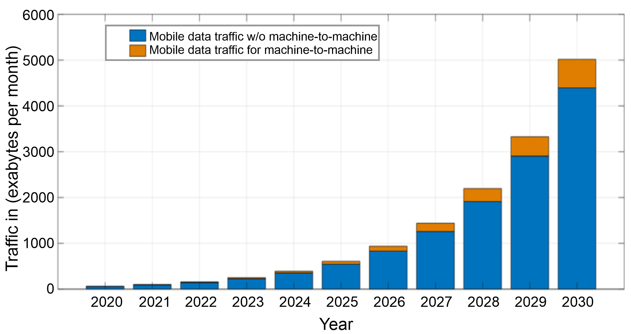
Fig. 1. Global mobile data traffic forecast for the period from 2020 to 2030 (Source: ITU).
To address the rising demand for data services, network operators are required to transition from traditional wireless systems to more efficient, high-bandwidth systems. One promising solution to address the limitations of overcrowded spectrum is the use of higher frequency bands, particularly in the millimeter-wave (mm-wave) range. The mm-wave band generally spans frequencies from 30 GHz to 300 GHz [3]. Nevertheless, generating mm-waves above 100 GHz remains challenging due to the performance limitations of available electronic components. As an alternative, optical methods for generating and transmitting mm-waves have emerged as an effective approach enabling the production of higher frequencies and allowing seamless integration with radio-over-fibre (RoF) systems. As a result, optical techniques for mm-wave generation have attracted considerable attention in recent years [4].
The fundamental mechanism for optical mm-wave generation is the optical heterodyne technique, in which optical signals from two independent laser diodes are combined and fed to a photodetector [5–8]. At present, various techniques have been used to generate mm-waves, including frequency upconversion [9], direct modulation [10], stimulated Brillouin scattering (SBS), four-wave mixing (FWM) [11–14], and external modulation techniques [15]. The frequency upconversion technique is simple to implement but suffers from increased phase noise. SBS and FWM have complex structures and restricted frequency multiplication factors (FMFs). In contrast, external modulation is widely regarded as a highly reliable technique for producing mm-wave signals as it offers large FMF and flexible frequency tuning. Several photonic approaches based on higher FMF, such as 16‑tupling and 32-tupling for mm-wave generation, have been reported in the literature. While these schemes aim to achieve higher FMFs, generating pure, stable mm-wave signals with a simplified configuration remains an important research objective. In our proposed work, two Mach-Zehnder modulators (MZMs) in a parallel configuration are employed to realise a filterless 8-tupling for the generation of a 40 GHz signal. However, several studies ‑ have already reported schemes for generating 8 tupling mm-wave signals. For instance, in one work, a 40 GHz mm-wave has been generated using a filterless RoF system, where the optical sideband suppression ratio (OSSR) is limited to 30 dB [16]. A re-modulation scheme using three MZMs is used in the work that increases the system complexity [17]. Furthermore, some approaches require high extinction ratios (ERs) of up to 100 dB, which is quite impractical for realistic implementations [18]. On the other hand, our proposed system achieves an OSSR of 50 dB and a radio frequency sideband suppression ratio (RFSSR) of 44 dB, demonstrating high spectral purity at a low modulation index of 2.868, which is advantageous for practical deployment. A generated 40 GHz signal falls within the frequency range widely used in high-capacity wireless links and RoF systems, where photonic generation of mm-wave carriers facilitates seamless optical-wireless integration.
The sections that follow are organised as detailed below. Section 2 presents the setup and principle of a frequency 8-tupling using dual-parallel MZMs (DPMZMs). Section 3 discusses the different results obtained in our work. Conclusions are given in section 4.
2. Setup and principle
The proposed system can be practically realised using standard optoelectronic components including a continuous wave (CW) laser diode, two lithium-niobate MZMs driven by RF signal generators, and a photodetector (PD). The system also contains electrical phase shifters (EPS), a polarisation controller (PC), a polarisation beam splitter (PBS), a polarisation beam combiner (PBC), a polariser (Pol), and an optical amplifier (OA). The functional arrangement of these components for a photonic generation of a 40 GHz mm-wave signal is illustrated in the block diagram shown in Fig. 2. The optical carrier signal from the CW laser passes through PC and then to PBS, where it is split into two beams along the x-axis and y-axis. The optical signal along the x-axis is split by the power splitter and fed to MZMa and MZMb. The two outputs of MZMa and MZMb are then fed to the polariser after passing through the PBC. The optical signal along the y-axis is directly fed to the PBC without modulation. The output from polariser is detected using a PD after amplification. MZMa and MZMb differ by a phase shift of 90°. The PC controls the optical power distribution ratio along the x- and y-axes. The values of the azimuth angle of PC and polariser angle are so adjusted that they cancel out the optical carrier component from the output of DPMZM. This leaves the ± 4th-order sidebands as the remaining components, which, after colliding in a PD, generate a 40 GHz mm-wave signal.
In practical implementations, deviations in bias point of the modulators and polarisation fluctuations may affect the system stability. These effects can be mitigated using automatic bias-control circuits and polarisation-control techniques that maintain the modulators operating conditions [19–21]. Such stabilisation techniques are widely used in the optical mm-wave generation and RoF systems.
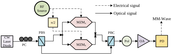
Fig. 2. Schematic of a frequency 8-tupling mm-wave generation based on DPMZMs, continuous wave (CW) laser diode, radio frequency (RF) source, polarisation controller (PC), polarisation beam splitter (PBS) and combiner (PBC), polariser (Pol), optical amplifier (OA), and photodetector (PD).
2.1. Output of DPMZM
The system uses two MZMs. The output of an MZM is given by the following standard expression:
In the above equation, Eo(t) and Ein(t) are the field strengths of the output and input optical signals, respectively, α is the attenuation coefficient due to insertion loss, γ is the power splitting ratio, νπ is the half-wave voltage of an MZM. Suppose the RF voltages on two arms of an MZM, ν1(t) and ν2(t), are expressed as vmcos(ωmt + ϕ) and vmcos(ωmt + φ + ϕ), respectively. Here, ϕ is the initial phase of the RF signal and φ is the phase difference between two RF driving voltages fed to two arms of an MZM. Substituting the values of ν1(t) and ν2(t) into (1), we get:

For MZM at MATP, φ = π and vbias1 = vbias2 = 0 V. For infinite ER as is the case with ideal MZM, splitting ratio is equal to 0.5. Thus, equation (2) reduces to:
where m = πvm/vπ is the modulation index of the MZMs so used.
Jacobi-Anger expansion is expressed as:
Therefore, we can write (3) as:
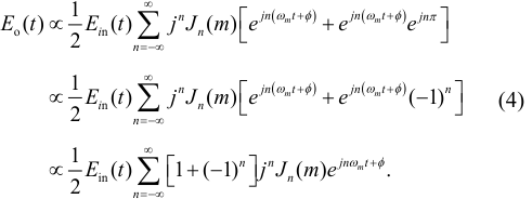
In (4), Jn(m) is the nth-order Bessel function of the first kind with argument m. For φ = π, creation of term [(−1)n+1] at output indicates the suppression of odd sidebands due to which equation (4) can be expressed as:

Now, MZMa and MZMb, differ by a phase of π/2, so the output of parallel combination of two MZMs can be expressed as:

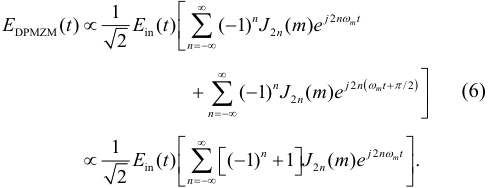
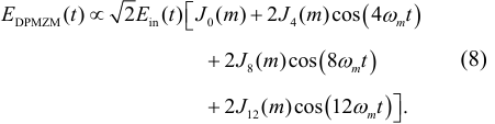
Due to the π/2 phase difference of two MZMs, again the term [(−1)n+1] is created and only ± 4th-order optical sidebands (as n takes values 0, ± 4, ± 8, ± 12, …) are present at the output of DPMZM. Therefore, (6) reduces to:

which can be further expressed as:
2.2. The elimination of unwanted optical sidebands
To obtain a 40 GHz high-purity mm-wave frequency from a 5 GHz RF signal, all the optical sidebands except the ± 4th-order need to be suppressed. The optical sidebands of ± 12th-order are very small and can be neglected according to the characteristic of Bessel functions. There is a need to suppress the optical carrier and ± 8th-order sidebands to a large extent.
Optical carrier is suppressed using a polarisation control method. Let Ein(t) = Einejωt represent the optical carrier wave, where Ein and ω are the amplitude and angular frequency of the carrier, respectively. The optical field at the output of the PBS can be expressed mathematically as:
where θ is the azimuth angle of PC, Ex and Ey are the field strengths of the optical carrier signals in the x-axis and y-axis directions of the system, respectively. Since Ey remains unmodulated and is fed directly to the PBC, by substituting the value of Ey from (9) into (8), we get:

The output optical signal from the polariser having a polarisation angle of π/4 is given by:
Putting value of EDPMZM(t) from (10) into (11), we get:
The carrier can be completely removed if:

From the above equation, the value of azimuth angle θ can be calculated as:

Now, after the removal of the optical carrier, (12) reduces to:

In order to suppress the ± 8th-order optical sidebands, we adjust the modulation index of the RF signal to make the coefficient of the 2nd term of (15) as small as possible. When the modulation index m is set to 2.868, the coefficient of the 2nd term is equal to 0.000704, which is quite small but not negligible. However, if m is set to 2.435, the 8th‑order sidebands are fully suppressed. But this results in the appearance of 1st-order sidebands. Thus, at m = 2.868, we find OSSR with respect to the 8th-order sidebands.
3. Results and discussion
For simulation purpose, OptiSystem software is used and the setup is illustrated in Fig. 2. The important parameters of the devices used in the simulation setup are mentioned in Table 1.
Important parameters of the devices used in the simulation set up.
| Parameters | Values |
|---|---|
| Frequency of RF source | 5 GHz |
| Amplitude of RF source | 3.65 |
| Centre frequency of laser diode | 193.1 THz |
| Line-width of laser diode | 10 MHz |
| Power of laser diode | 10 dBm |
| Azimuth of polarisation controller (θ) | 6.78° |
| Gain of optical amplifier | 30 dB |
| Noise figure of optical amplifier | 4 dB |
| Responsivity of photodiode | 0.8 A/W |
| Dark current of photodiode | 10 nA |
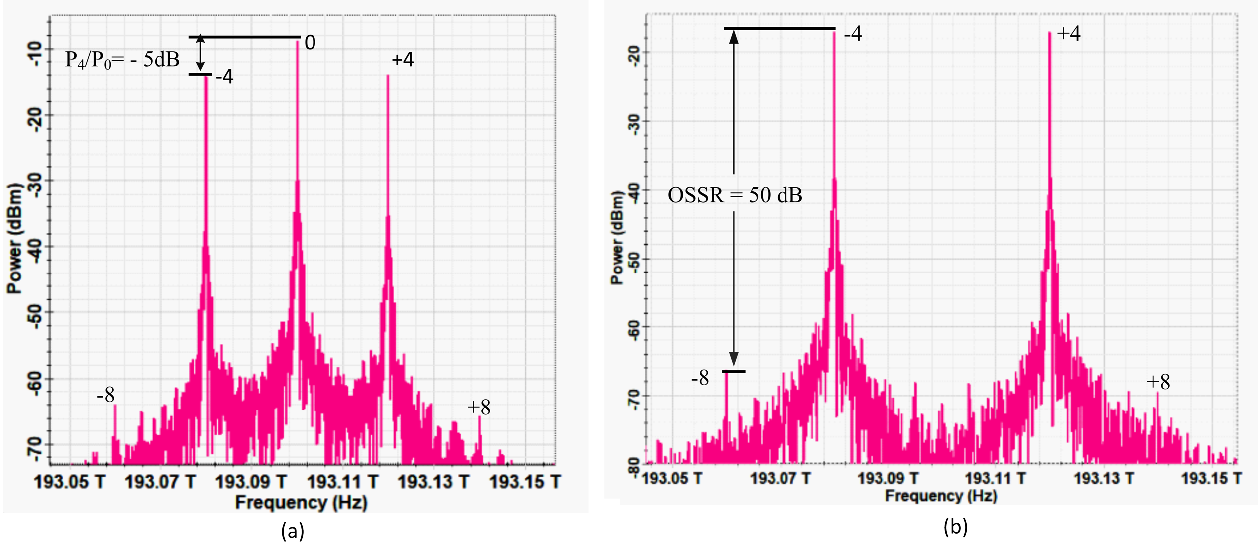
Figure 3(a) shows the signal at the output of an optical combiner. The spectrum reflects the presence of ± 4th-order optical bands along with an unsuppressed carrier. All other sidebands except the ± 8th-order sidebands are negligibly small. The ratio of the 4th-order sideband with respect to zero-order sideband, P4/P0 = −5 dB [see Fig. 3(a)]. This can be verified mathematically for m = 2.868, as:

Figure 3(b) shows the spectrum of an optical signal at the polariser, where the carrier is effectively suppressed when the polariser angle is set to 45°. The largest spurious sidebands are around 8th-order and are around 50 dB lower than the desired 4th-order sidebands.
Fig. 3. (a) Optical spectrum at optical power combiner, (b) optical spectrum at polariser.
The same is verified mathematically, where the OSSR is calculated to be equal to 50.28 dB as shown below:

When an output optical signal from DPMZM is beaten into PD, a 40 GHz signal is generated. The output in the form of a photocurrent from PD having responsivity R after passing through an OA of gain G is given by:
Putting value of Epol(t) from (15) into (18), we get:
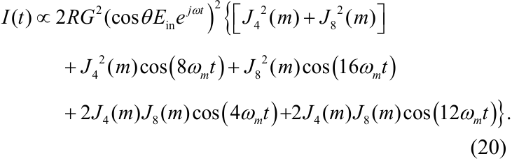
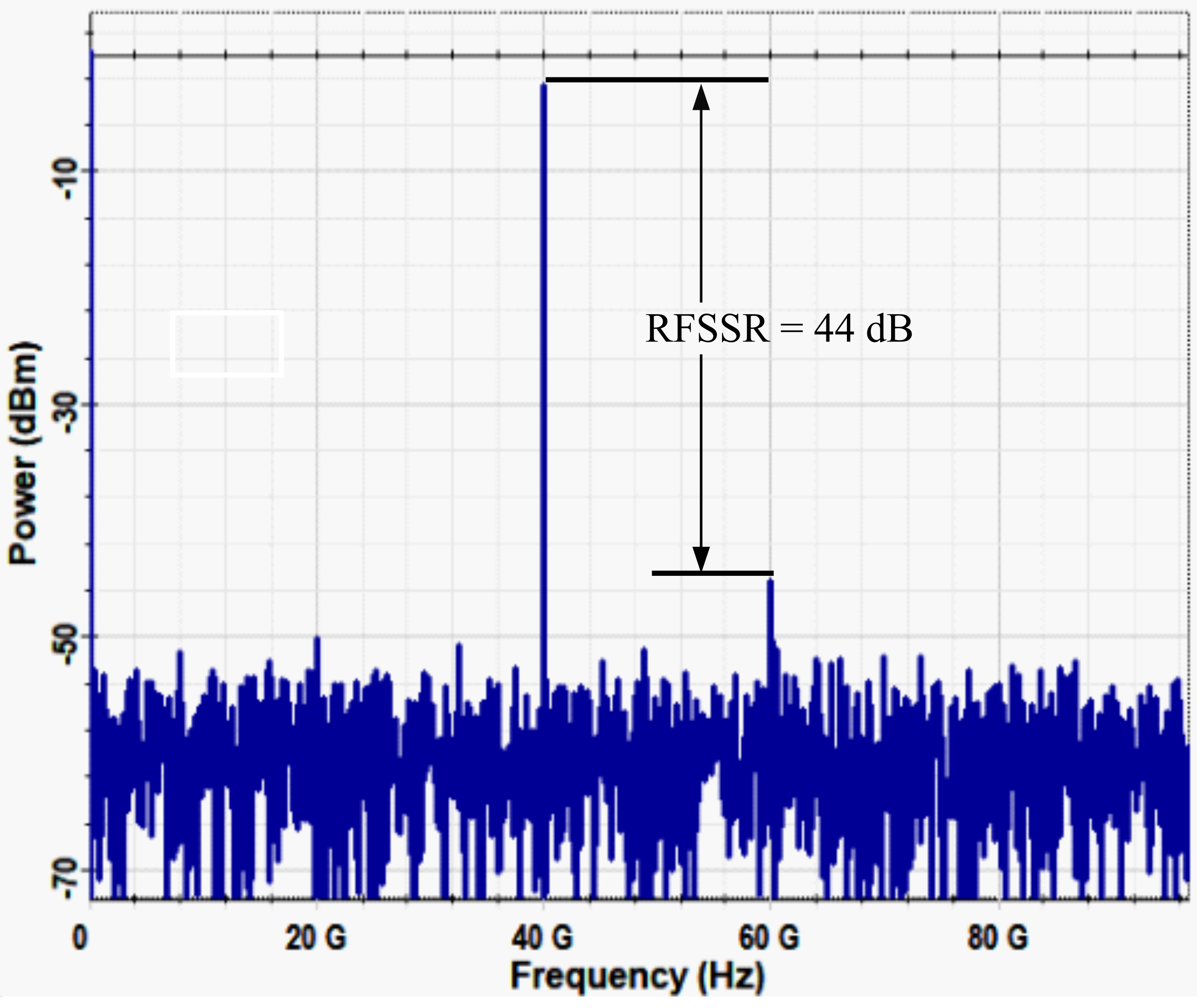
In (20), the term [J42(m) + J82(m)] corresponds to the DC component and the cosine terms represent the harmonic components used to evaluate the RFSSR. The 8th harmonic of RF signal having the largest amplitude is the desired signal. The value of J82(2.868) = 1.24 × 10⁻⁷ is a negligibly small value and thus 3rd term can be omitted. The value of J4(2.868)J8(2.868) = 4.05 × 10⁻⁵. This shows that 4th- and 12th-order harmonics are the largest spurious signals present, which is also suggested by Fig. 4, where RFSSR is seen to be equal to 44 dB. This value is quite close to the calculated value justified below:

The main parameters that affect the purity of the mm-wave signal are ER, amplitude, azimuth angle, and the RF signal initial phase. Therefore, it becomes necessary to analyse the effect on SSR by varying these parameters.
3.1. Effects of variation of modulation index (m) and azimuth angle (θ) on OSSR and RFSSR
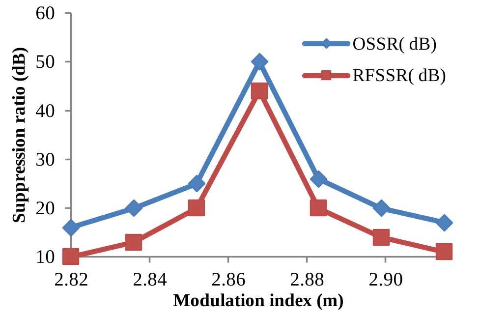
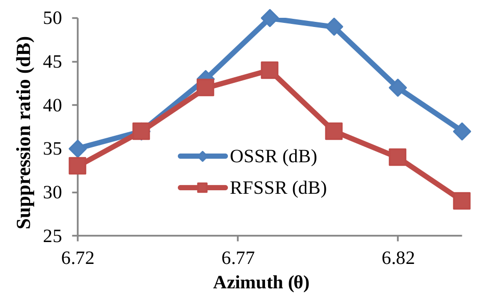
Figure 5(a) shows the variation of OSSR and RFSSR with respect to the modulation index (m). It is seen that both the OSSR and RFSSR reach their maximum value at m = 2.868. At this value of m, OSSR and RFSSR are found to be nearly equal to 50 dB and 44 dB, respectively. Figure 5(b) shows a plot between suppression ratio and azimuth angle of PC (θ). At θ = 6.78°, OSSR and RFSSR are the maximum values. However, for θ = 6.72° to 6.84°, OSSR and RFSSR both are ≥ 30 dB. OSSR and RFSSR both are ≥ 20 dB for the modulation index range of 2.852 to 2.883.
(a)
(b)
Fig. 5. (a) Effects on OSSR and RFSSR with change in modulation index, (b) effects of change in azimuth angle (θ) on OSSR and RFSSR.
3.2. Effects of variation of extinction ratio (ER) on sideband suppression ratio (SSR)
The splitting ratio is given by the equation, $\gamma=\left(1-\frac{1}{\sqrt{\epsilon_{\text{r}}}}\right)/2$.
Here, $\epsilon_{\text{r}}=10^{\frac{\text{ER}}{10}}$, where ER is the extinction ratio of an MZM. Most of the commercial optical MZMs have an ER around 30 dB which results in low-power spurious optical sidebands. Figure 6 depicts the effect on the suppression ratio with a change in ER.
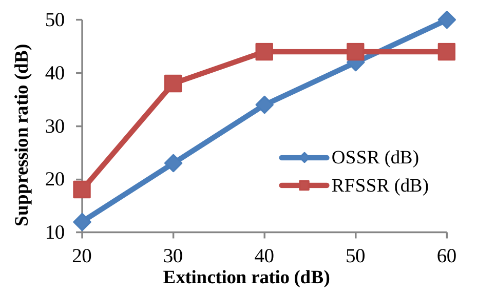
Fig. 6. Effects of change in ER on OSSR and RFSSR.
The OSSR improves linearly as the ER is increased beyond 30 dB. Beyond an ER of 40 dB, the OSSR is ≥ 34 dB, but RFSSR saturates and remains constant at a maximum value of 44 dB.
4. Conclusions
This work presents a method to generate an mm-wave signal at 40 GHz from a 5 GHz RF source using a single DPMZM. The proposed system generates a carrier band and 4th-order optical sidebands at a modulation index of 2.868. A polarisation control method is used to suppress the carrier, which is an energy-efficient approach. Further, an investigation is carried out to analyse the variation of OSSR and RFSSR with the change in parameters like the ER of MZMs, the azimuth angle of PC, and the amplitude of the RF drive signal. The theoretically calculated values of OSSR and RFSSR for the generated signal, 50.28 dB and 44.23 dB, respectively, are supported by simulation results, which were found to be 50 dB and 44 dB, respectively.
Authors’ statement
The authors declare that there is no conflict of interest.
References
[1] Fito, V. et al. Performance evaluation of dual-drive Mach-Zehnder modulator and optomechanical crystal cavity comb generation for all-optical band conversion in 5G-advanced cellular systems. IEEE Photon. J. 17, 7200409 (2025). https://doi.org/10.1109/JPHOT.2025.3532177
[2] Tariq, F. et al. A speculative study on 6G. IEEE Wirel. Commun. 27, 118–125 (2020). https://doi.org/10.1109/MWC.001.1900488
[3] Chen, X., Chen, Hu., Dai, S., Li, B. & Wang, L. A novel frequency 32-tupling ROF system without bit walk-off effect based on MZM with inserting pilot. Heliyon 10, e32871 (2024). https://doi.org/10.1016/j.heliyon.2024.e32871
[4] Wang, X., Ren, L., Yang, X. & Wang, D. A scheme for generating millimeter wave signals through 32-tupling frequency multiplication without filtering using eight Mach-Zehnder modulators. Mathematics 12, 2781 (2024). https://doi.org/10.3390/math12172781
[5] Stohr, R. H., Heinzelmann, A., Malcoci, A. & Jager, D. Optical heterodyne millimeter-wave generation using 1.55-/spl mu/m traveling-wave photodetectors. IEEE Trans. Microw. Theory Tech. 49, 1926–1933 (2001). https://doi.org/10.1109/22.954809
[6] Browning, C., Delmade, A., Lin, Y., Geuzebroek, D. H. & Barry, L. P. Optical Heterodyne Millimeter-Wave Analog Radio-OverFiber with Photonic Integrated Tunable Lasers. in Optical Fiber Communication Conference (OFC) W1I.4 (Optical Society of America, 2019).
[7] Li, X., Xiao, J., Xu, Y. & Yu, J. QPSK vector signal generation based on photonic heterodyne beating and optical carrier suppression. IEEE Photon. J. 7, 7102606 (2015). https://doi.org/10.1109/JPHOT.2015.2486685
[8] Chen, X. et al. Filterless frequency 32-tupling millimeter-wave generation based on two cascaded dual-parallel Mach-Zehnder modulators. Front. Phys. 11, 1212482 (2023). https://doi.org/10.3389/fphy.2023.1212482
[9] Yu, Y., Dong, J., Li, X. & Zhang, X. Photonic generation of millimeter-wave ultra-wideband signal using phase modulation to intensity modulation conversion and frequency up-conversion. Opt. Commun. 285, 1748–1752 (2012). https://doi.org/10.1016/j.optcom.2011.12.041
[10] Chen, L., Pi, Y., Wen, H. & Wen, S. All-optical mm-wave generation by using direct-modulation DFB laser and external modulator. Microw. Opt. Technol. Lett. 49, 1265–1267 (2007). https://doi.org/10.1002/mop.22449
[11] Al-Dabbagh, R. K, & Al-Raweshidy, H. S. Photonic methods of millimeter-wave generation based on Brillouin fiber laser. Opt. Laser Technol. 79, 124–131(2016). https://doi.org/10.1016/j.optlastec.2015.12.005
[12] Park, C.-S., Lee, C.-G. & Park, C.-S. Photonic frequency upconversion by SBS-based frequency tripling. J. Light. Technol. - 25, 1711–1718 (2007). https://doi.org/10.1109/JLT.2007.897749
[13] Zheng, H., Liu, S., Li, X., Wang, W. & Tian, Z. Generation and transmission simulation of 60 G millimeter-wave by using semiconductor optical amplifiers for radio-over-fiber systems. Opt. Commun. 282, 4440–4444 (2009). - https://doi.org/10.1016/j.optcom.2009.08.023
[14] Shih, P.-T. et al. Optical millimeter-wave signal generation via frequency 12-tupling. J. Light. Technol. 28, 71–78 (2009). https://doi.org/10.1109/JLT.2009.2035452
[15] Wu, P. & Ma, J. BPSK optical mm-wave signal generation by septupling frequency via a single optical phase modulator. Opt. Commun. 374, 69–74 (2016). https://doi.org/10.1016/j.optcom.2016.04.057
[16] Wu, Z. et al. Filterless radio-over-fiber system to generate 40 and 80 GHz millimeter-wave. IEEE Photon. J. 12, 5502313 (2020). https://doi.org/10.1109/JPHOT.2020.3020596
[17] Chen, X. et al. A novel method to generate and transmit 40-tupling frequency millimeter wave over fiber based on remodulation of MZMs. Heliyon 9, e14221 (2023). https://doi.org/10.1016/j.heliyon.2023.e14221
[18] Guo, X. et al. Generation of 40-GHz Millimeter-Wave Signals based on Radio-over-Fiber system Employing Optical Frequency Quadrupling Scheme . in Optical Transmission Systems, Subsystems, and Technologies Conference 83092C (Optica Publishing Group, 2011), https://doi.org/10.1364/ACP.2011.83092C
[19] Choi, D., Kim, S. & Won, Y.-Y. Automatic bias control of MachZehnder modulator using RMSProp-based gradient feedback optimization. Opt. Quantum Electron. 57, 465 (2025). https://doi.org/10.1007/s11082-025-08391-x
[20] Teng, J. et al. Arbitrary bias control of LiNbO3-based MachZehnder intensity modulators for QKD system. EPJ Quantum Technol. 10, 33 (2023). https://doi.org/10.1140/epjqt/s40507-023-00189-8
[21] Damask, J. N. Polarization Optics in Telecommunications. (Springer, New York, 2005).