Two cascaded, dual-parallel Mach-Zehnder modulators (DP-MZMs) at 2.5 and 5 GHz radio frequency (RF) transmissions, along with 36-tupling in radio over fibre (RoF), have been suggested for a millimeter wave generation at 90 GHz and 180 GHz. To optimize the quality of the signal, the performance of the generated millimeter wave was assessed at the receiver. The bit rate was successfully adjusted up to 20 Gbps over a 50 km single-mode fibre to verify the system ability and manage a greater data flow. The proposed parametric research is graphically analysed at 10 and 20 Gbps with a minimal bit error rate (BER) of 10–9. Fibre length, BER, quality factor, optical sideband suppression ratio (OSSR), and radio frequency sideband suppression ratio (RFSSR) are considered for performing the characteristics analysis. This research provides an extremely high-frequency multiplication factor for major applications in millimeter wave technology.
Introduction
A three-arm Mach-Zehnder modulator (MZM) is a revolu-tionary way to create an optical frequency doubling millimeter wave signal using radio over fibre (RoF) optic networks. A unique approach [1] has been used to develop a RoF link through simulation to demonstrate the data transfer performance of the proposed technique and reported that after more than 40 km of transmission, the eye diagram is still open and visible. A study on the transmission performance of a double-tone optical millimeter wave operating at 40 GHz has also been carried out using a single dual-electrode MZM, as described in [2], to quadruple the frequency of a radio local oscillator by utilizing the transmission function of the dispersive fibre. Three dual-electrode MZMs are used in a dual-electrode dual-parallel combined MZM as the basis for the demonstrated frequency quadrupling system in [3] to create optical millimeter wave signals. A millimeter wave signal with a phase variation of π/4 produced by an electrical phase shifter can be obtained by converting a sextuple frequency multiplication of a microwave source [4] employing two cascaded optical modulators. Without an optical filter, a frequency-sextupled microwave signal can be generated using an integrated dual-polarization modulator [5] to obtain a pure frequency-sextupled signal with an optical sideband suppressing ratio (OSSR) over 38 dB and a radio frequency sideband suppressing ratio (RFSSR) above 32 dB. A novel frequency sextupling method based on the integrated MZM (IMZM) laser has been proposed for generating millimeter wave signals in RoF systems [6] and resulted an OSSR exceeding 29 dB without the need of an optical filter when the IMZM is composed of three sub-MZMs that have an extinction ratio of 30 dB. This study demonstrated the generation of wideband frequencies of octuple optical millimeter wave signals without a filter. An MZM drive and a polarization control system are the two essential components used within the frequency range of 4 to 80 GHz [7], reaching the necessary 34 dB sideband suppression ratios. The generation of millimeter waves or the recovery of optical carriers [8] at a 80 GHz frequency has been achieved by manipulating the polarization direction.
This study suggests a simplified filterless frequency octupling technique by connecting a dual-parallel Mach-Zehnder modulator (DP-MZM) in series with an intensity modulator. According to the simulation results [9], 4 and 5 GHz local oscillator frequencies are used to generate millimeter waves at 32 and 40 GHz, respec-tively, and an acceptable phase noise of 15 dB electric suppression ratio is reported. Numerical simulation [10] produced millimeter wave signals at 20, 40, and 60 GHz, conveying a 2.5 Gbps transmission via a 2.5 GHz RF signal. A Mach-Zehnder interferometer is proposed [11] consisting of two pairs of MZMs coupled in series on each arm to perform optoelectronic frequency multiplication (8- and 24-tupling). Zhu et al. suggested a novel method [12] for selectively producing millimeter waves at 120 GHz from a local oscillator operating at 10 GHz using an integrated layered MZM. Two cascaded MZMs are used to create a millimeter-wave signal that is 16 times higher in frequency than the original RF and the signal is sent over fibre distances of 10, 20, and 25 km utilizing a 2.5 Gbps RoF system [13].A new filterless technique for exploiting the polarization property at a 160 GHz 16-tupled milli-meter wave signal was studied in [14] with a 10 GHz RF local oscillator frequency. In order to overcome the bit walk-off problem, a new inserting pilot method that uses MZMs has been used to generate and send a 16-tuple millimeter-wave radio signal via a fibre system [15]. A potential RoF system design using optical millimeter wave technology with 18-tuple frequencies and a 20 km fibre length at 90 GHz was published in [16].
In [17], a new technique for filterless frequency 32-tupling millimeter wave generation based on two cascading DP-MZMs was noted with experimental and theoretical OSSRs of 53.7 dB and 53.53 dB, respectively, as well as radio frequency sideband suppression ratios (RFSSRs) of 47.7 dB and 47.33 dB, using 32-tupling of the millimeter-wave radio across a fibre system, as reported in [18]. Furthermore, the occurrence of bit walk-off was eliminated. The research was proposed in [19] for generating millimeter wave signals with a photonically-assisted technology for contemporary space applications. Two designs, the dual-drive MZM and the amplitude modulator, are examined for this purpose using various optical modulators. The single-sideband modulation approach [20] was found to eliminate the code edge time shift during the signal transfer in the RoF system. The simulation results demonstrate that the updated single-sideband modulation approach achieves an accuracy factor of 23.362, having a sending distance of 73.453 km, a clean eye diagram, and a minimal bit error rate (BER) of 4.207 × 10⁻¹²⁷. By providing the required phase shifts and suitably modifying the MZM as biasing points, as well as modulation index values, it is possible to effectively create a single setup used to attain different tupling factors, such as 2, 4, 6, 8, 10, and 12 [21]. Using a data rate of 2.5 Gbps and a 24-tupling millimeter wave generation without optical filters [22] achieves OSSR higher than 33 dB and RFSSR better than 26 dB. Using polarization multiplexing [23] for carrier suppression, the authors described the development of the 24-tupled millimeter wave signal through integrating three cascaded MZMs. A semicon-ductor laser with optical injection has been used to experimentally show high-purity millimeter waves in the 60 GHz region. According to a microwave signal at 65.07 GHz with (FM, PM) = (7.23 GHz, 13.00 dBm) and a millimeter-wave signal at 61.28 GHz with (FM, PM) = (15.32 GHz, 20.00 dBm) were modulated with 1/4 and 1/9 sub-harmonics, respectively, as in [24]. Additionally, a study in [25] investigated the comparison of various edge shapes of return to zero (RZ) and non‑return to zero (NRZ) modulation formats for RoF and free-space optics (FSO) which are emerging and potential technologies for an optical-domain millimeter wave generation, as well as access network solutions in 5G and 6G mobile networks.
This study employs two cascaded DP-MZMs to generate millimeter waves with a frequency 32-tupling in the RoF system, achieving enhanced OSSR and RFSSR signals. The performance of BER, OSSR, RFSSR, and quality factor at 90 GHz and 180 GHz frequencies has been examined. In optical communication systems, a higher OSSR denotes better suppression of the undesired sideband, which improves signal quality and efficiency. The undesirable sidebands are substantially suppressed compared to the intended RF signal when the RFSSR value is higher.
Theoretical analysis
Continuous wave (CW) operation refers to a laser ability to pump and produce light constantly. A 1550 nm wave-length laser has been used in this study and the CW laser frequency can be calculated as f:
The RF signal electrical voltage amplitude and angular frequency are represented by Vm and ωm, respectively. Assuming that MZM1 and MZM2 operate at their highest transmission points and that an initial phase difference of π/2 exists between them, the outcomes from DP-MZM1, MZM1, and MZM2 are given by (5):
\(
\begin{aligned}
& E_{\mathrm{M} Z \mathrm{M} 1}(t)=2 \alpha E_{\mathrm{in}}(t) \sum_{n=-\infty}^{n=\infty}(-1)^n J_{4 n}(m) e^{i_{4 n} c_{\infty} t}, \\
& E_{\mathrm{M} Z \mathrm{M} 1}(t)=2 \alpha E_{\mathrm{in}}(t) \sum_{n=-\infty}^{n=\infty}(-1)^n J_{4 n}(m) e^{i_{4 n} c_m t} e^{\frac{j n \pi}{2}} \\
& E_{\mathrm{DP}-\mathrm{M} Z \mathrm{M} 1}(t)=E_{\mathrm{M} Z \mathrm{M} 1}(t)+E_{\mathrm{M} Z \mathrm{M} 1}(t), \\
& E_{\mathrm{DP}-\mathrm{M} Z \mathrm{M} 1}(t)=4 \alpha E_{\mathrm{in}}(t) \sum_{n=-\infty}^{n-\infty} J_{8 n}(m) e^{j_{8 n} c_n t} .
\end{aligned}
\) (5)
In this case, α represents the insertion loss, m = πVm/VπRF denotes the MZM modulation index, and VπRF represents the MZM half-wave voltage.
Assuming that MZM3 and MZM4 operate at their maximum transmission points and there is a phase difference of π/2 between them, their output characteristics follow accordingly. Equation (6) represents the DP-MZM2, MZM3, and MZM4 outputs. Comparable, the following equation (6) represents how DP-MZM2 structure is formed:
Equation (8) states the DP-MZM output signal, which contains ± 16n-level optical sidebands. To acquire pure ± 16 n-level sidebands, m is selected at 18.080.
MZM5 uses ± 16th order optical sidebands for the optical carriers to produce the output signal when it is operating at its maximum transmission points. The RF
Equation (10) states the DP-MZM and the single MZM output signal is the second transmission of the signal. The authors substitute the MZM5 value and simplify (11).
where β represents the insertion loss of the MZM5 modula-tion index, β = πVβ/VπRF, and VπRF is the MZM5 half-wave voltage.
Once the optical signal from the DP-MZM is received for the photoelectric conversion, the output current from the photodetector is obtained and can be expressed as follows:
where R represents the photodetector responsivity.
OSSR refers to the power ratio between the desired optical signal sideband and the unwanted sideband, essentially measuring how effectively the unwanted sideband is suppressed, is typically expressed in dB:
RFSSR refers to how effectively unwanted, extraneous RF sidebands generated during optical modulation are suppressed. By comparing the targeted RF signal strength to these suppression sidebands power, it effectively reveals the signal quality.
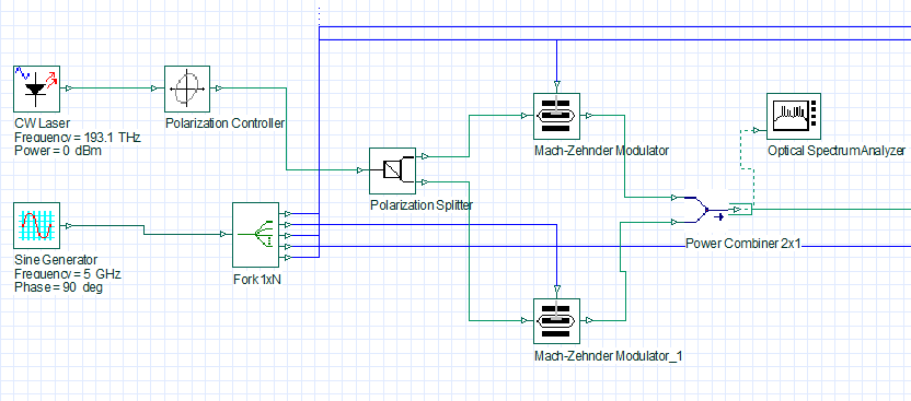
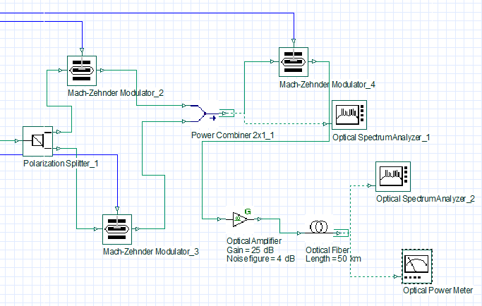
Mobile frontline hauling uses RoF, a significant advance-ment in networking technology, to integrate wired and wireless networks. For the millimeter-wave RoF transmis-sion technology, photonic production of a millimeter-wave signal is an essential component. The photonic conversion technique uses millimeter wave RoF to transform an optical signal into a radio transmission at very high frequencies. To achieve reliable transmission and meet performance requirements, the MZM is employed for photonic processing to produce millimeter waves that can be used for data transmission. The frequency multiplication factor, or fRF, can be increased to produce a millimeter wave with a higher frequency. Upgrading a frequency multiplier is used since its frequency response range and electronics price restrict the fRF. There are several suggestions for MZM-dependent approaches that can be used to generate millimeter waves using frequency multiplication factors such as 8, 12, 16, 24, and 32. The authors’ proposal involved the use of filterless MZM to produce high-purity millimeter wave signals with a 36-tupling frequency. These frequency multiplication techniques were used to transmit the generated millimeter wave signals with bit rate up to 20 Gbps over a 50 km single-mode fibre distance. The broadband dual-parallel MZM schematic for the millimeter wave generation at 36‑tupling frequency is displayed in Fig. 1. A CW laser, optical amplifiers, single-mode fibre, polarizing controller, power combiner, RF signal generator, and photodetectors make up the system. An optical signal carried by CW lasers is received by the polarization controller. The light from the top branch is divided into two beams by an optical polarization splitter, directing them toward MZM1 and MZM2, respectively. With the combined electrical power of the optical combiner and splitter, the optical impulse outputs at MZM1 and MZM2 are combined into a single beam.
Fig. 1. Schematic design for generating a 36-tupling millimeter
wave signal.
This beam is injected into half at MZM3 and MZM4 and gets combined in the power combiner between the MZM3 and MZM4 terminals. The MZM5 output optic signals first pass through an optical amplifier and an optical fibre before being sent to the photodetector to complete the photoelectric conversion.
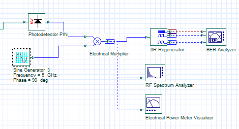
Table 1 compiles the primary parameters used in the simulation setup of Fig. 2(a) and 2(b), with Fig. 2(c) that displays the components integrated into the simulation for the PIN photodiode design 36-tuple transmitter, as well as the receiver side.
Fig. 2. DP-MZM using 36-tupling in (a) RoF system,
(b) transmitter design, (c) receiver design.
The DP-MZM could generate optical sidebands of ± 4n order as a quadrupling. Two separately cascading DP-MZMs can act as 16-tupling to produce optical sidebands of order of ± 16n. After suppressing the centre carrier, the lesser amplitudes in ± 16n (n > 2) sidebands are ignored by modifying the MZMs index of modulation. Single MZM generates 4 optical sidebands (± 2nd order), and thereby two cascaded DP-MZMs result in 32 optical sidebands. As seen in Fig. 2(c), the greatest signal in the entire spectrum of the signal produced by the millimeter wave signals from the light detector are 90 and 180 GHz, which is 36 times the range of RF signals from 2.5 and 5 GHz.
Simulation results and discussion
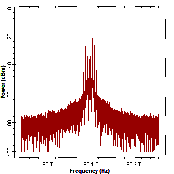
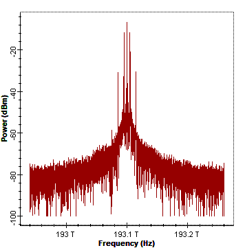
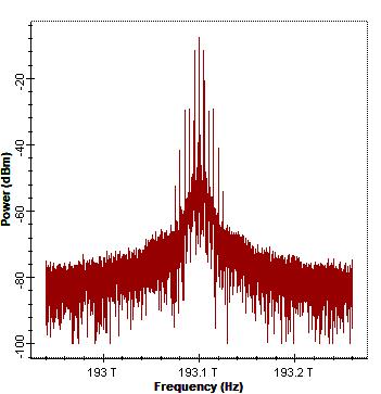
In order to obtain a 36-tuple frequency, the CW laser and RF signals pass via MZM1 to MZM5, which is designed with 36 optical sidebands using DP-MZM. This 36-tupling frequency millimeter wave over fibre system performance is estimated by setting up a RoF simulation result using photonic simulation software, as seen in Fig. 3. The optical spectrum output of MZM1 and MZM2, after passing through the power combiner, exhibits a signal frequency of 193.1 THz, as shown in Fig. 3(a). As shown in Fig. 3(b), the power combiner output in the optical spectrum analyser is achieved by combining MZM3 and MZM4. The outcome of the power combiner shows the signal frequency which is 193.1 THz.
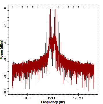
Fig. 3. Spectrum output at power combiner for (a) MZM1 and MZM2, (b) MZM3 and MZM4, (c) MZM5, (d) after the single-mode fibre
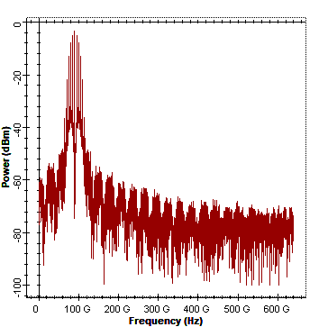
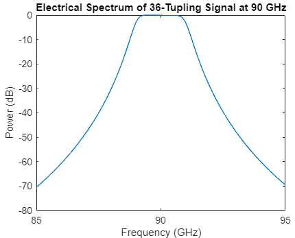
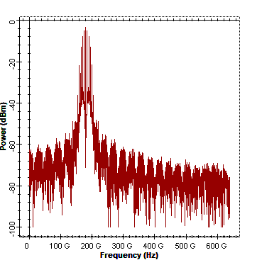
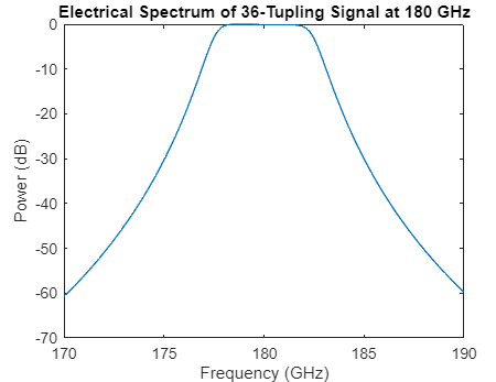
channel. Millimeter wave power spectrum at 90 GHz and 180 GHz – (e) and (g) using simulation (f) and (h) by MATLAB 180 GHz,
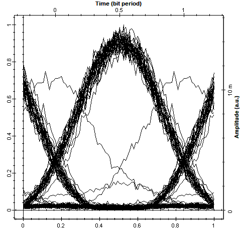
(i) BER pattern.
The MZM5 optical spectrum shows a 36 harmonic optical sideband with a maximum output power range of −4.410 dBm at 193.1 THz signal frequency as in Fig. 3(c). After passing through the optical amplifier, the MZM5 output is obtained with amplification. Fig. 3(d) shows the analysis of the single-mode fibre output examined using an optical spectrum analyser operating at a frequency of 193.1 THz. The optical signal is converted to an electrical signal by a photodetector and visualized using the spectrum analyser.
The input, carrier, or RF frequency is 2.5 GHz, which generates the 36-tupling system to produce the RF output frequency at 90 GHz. The RF millimeter wave generation is shown in Fig. 3(e). This RF output at 90 GHz has been proved using a MATLAB code which shows the frequency vs. power spectrum using the fast Fourier transform (FFT) for the 36-tuple generation as shown in Fig. 3(f). For further analysis, the input, carrier, or 5 GHz RF frequency generates a 36-tupling system to produce the RF output frequency at 180 GHz as shown in Fig. 3(g). This RF output at 180 GHz has been proved using a MATLAB code with the frequency power spectrum relation using the FFT for the 36-tuple generation, as in Fig. 3(h). The RF signal is analysed using the BER pattern using the BER analyser, as shown in Fig. 3(i).
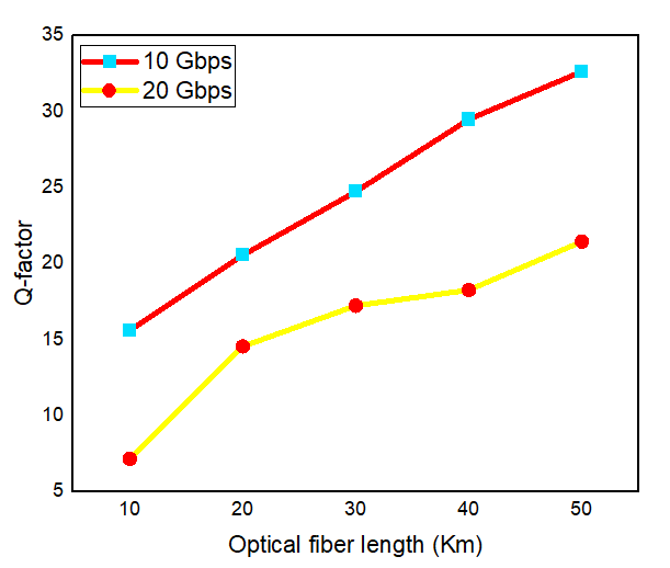
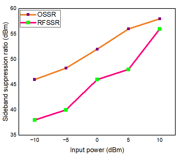
As illustrated in Fig. 4(a), the fibre optical length was adjusted for the Q-factor from 10 to 50 km at data transfer rates of 10 and 20 Gbps in order to carry out the parametric analysis. The graph indicates that the quality factor also increased for both data rates due to increased fibre length. According to input and output power, OSSR and RFSSR have been plotted as seen in Fig. 4(b).
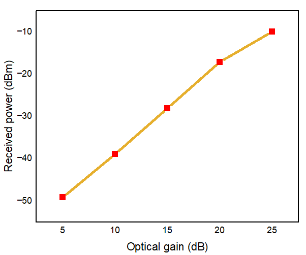
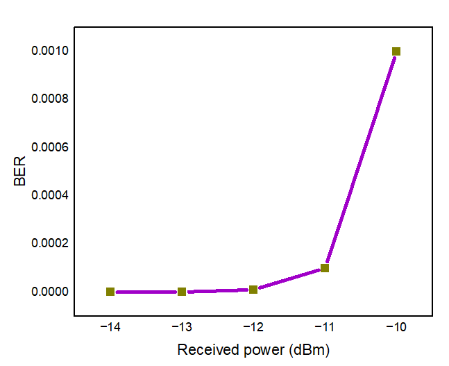
Fig. 4. (a) Optical fibre length vs. quality factor, (b) input power vs. OSSR and RFSSR, (c) gain vs. received power (dBm),
(d) received power (dBm) vs. BER.
The sideband suppression ratio is also increased for the CW laser input from −10 to +10 dBm. The received power (dBm) in millimeter wave generation has been plotted regarding the optical gain of power amplifiers from 5 to 25 dB as in Fig. 4(c). The RF signal received power rises in tandem with the growth of the optical gain. Fig. 4(d) illustrates the BER as a function of the received power at the photodetector for an optical fibre length ranging from 10 to 50 km. As the received optical power decreases, the BER reaches zero when the received power is approxi-mately −13 dBm and −14 dBm.
RFs driving the signal are at frequency fRF, while the frequency of the millimeter wave produced by MZMs is 2nfRF. Two times the frequency, or n, is the frequency multiplication factor by MZM which produces the desired sideband to generate millimeter waves of higher frequency. However, this frequency response has been limited by the cost of electronics. Table 2 compares OSSR and RFSSR at millimeter wave generation by the multiplication factors, including 8, 12, 16, 24, and 32 for frequency.
Comparison of millimeter wave generations of OSSR and RFSSR for a multiplication factor of 8 to 36.
Frequency multiplication factor (FMF)
OSSR (dB)
RFSSR (dB)
8
20
10
12
25
20
16
24
18
24
19
14
32
28
30
36
52
46
Both RFSSR and OSSR improve with an increase in the FMF. A higher ratio indicates better suppression of the unwanted sideband. A higher RFSSR means better suppres-sion of unwanted sidebands. The 36-tupling RoF system simulation results in 52 dB in OSSR and 46 dB in RFSSR, respectively, for transmission distances up to 50 km.
The main standards for evaluating the quality of the produced millimeter wave signal are OSSR and RFSSR. For wireless communication applications, the RFSSR typically has a range of > 5 dB to contrast two cascaded DP-MZMs as suggested in terms of the main features of millimeter wave generation. Table 3 compares these values with other works done so far. In the research proposal, it is found that the signal quality has been improved with lower error levels over a 50 km optical distance at a data rate of 20 Gbps.
This research established a 36-tupling frequency method of millimeter wave generation employing two cascaded DP‑MZMs. The OPTISYSTEM and MATLAB code were successfully used to generate millimeter wave and centre frequency validation. A transmission range of 50 km has been attained with 90 and 180 GHz millimeter wave frequencies at a data throughput of 20 Gbps. Based on simulation and theoretical study, the modulation signal has an OSSR of 52 dB and RFSSR of 46 dB. A parametric analysis was performed on fibre length, quality factor, BER, received power, OSSR, and RFSSR. Future wireless networks will benefit from millimeter wave frequencies and fibre technologies for communication. They might use the improved technology, providing an increased data rate, large bandwidth, low cost, and large capacity. This research proposes an attractive option for wireless RoF networks that use millimeter wave execution in 5G technology.
References
Chen, Y., Wen, A., Yin, X., Shang, L. & Wang, Y. Generation of frequency-doubling mm-wave signal using a Mach-Zehnder modulator with three arms to overcome fiber chromatic dispersion. Opt. Fiber Technol. 18, 1–6 (2012). https://doi.org/10.1016/j.yofte.2011.09.003
Zhou, M. & Ma, J. The influence of fiber dispersion on the transmission performance of a quadruple-frequency optical millimeter wave with two signal modulation formats. Opt. Switch.Netw. 9, 343–350 (2012). https://doi.org/10.1016/j.osn.2012.04.001
Yu, S., Gu, W., Yang, A., Jiang, T. & Wang, C. A frequency quadrupling optical mm-wave generation for hybrid fiber-wireless systems. IEEE J. Sel. Areas Commun. 31, 797–803 (2013). https://doi.org/10.1109/jsac.2013.sup2.12130012
Zhang, J., Chen, H., Chen, M., Wang, T. & Xie, S. Photonic generation of a millimeter-wave signal based on sextuple-frequency multiplication. Opt. Lett. 32, 1020–1022 (2007). https://doi.org/10.1364/OL.32.001020
Zhu, Z., Zhao, S., Li, X., Qu, K. & Lin, T. Filter-free photonic frequency sextupler operated over a wide range of modulation index. Opt. Laser Technol. 90, 144–148 (2017). https://doi.org/10.1016/j.optlastec.2016.10.010
Shi, P. et al. A frequency sextupling scheme for high-quality optical millimeter-wave signal generation without optical filter. Opt. Fiber Technol. 17, 236–241 (2011). https://doi.org/10.1016/j.yofte.2011.02.007
Qin, Y., Sun, J., Du, M. & Liao, J. Simplified optical millimeter- wave generation configuration based on frequency octupling. Opt. Commun. 315, 280–285 (2014). https://doi.org/10.1016/j.optcom.2013.11.033
Fan, S. et al. A RoF system based on polarization multiplexing and carrier suppression to generate frequency eightfold millimeter wave. Res. Phys. 12, 1450–1454 (2019).https://doi.org/10.1016/j.rinp.2019.01.052
Zhang, W. et al. A simplified filterless photonic frequency octupling scheme based on cascaded modulators. J. Mod. Opt. 64 , 861–865 (2017). https://doi.org/10.1080/09500340.2016.1262917
Zhou, H., Shen, Y., Chen, M., Cheng, J. & Zeng, Y. A RoF access network for simultaneous generation and transmission multiband signals based on frequency octupling and FWM techniques. Adv. Condens. Matter Phys. 2018, 409583 (2018). https://doi.org/10.1155/2018/9409583
Hasan, M. & Hall, T. J. A photonic frequency octo-tupler with reduced RF drive power and extended spurious sideband suppression. Opt. Laser Technol. 81, 115–121 (2016). https://doi.org/10.1016/j.optlastec.2016.01.039
Esakki Muthu, K., Sivanantha Raja, A. & Shanmugapriya, G. Frequency 16-tupled optical millimeter wave generation using dual cascaded MZM and 2.5 Gbps RoF transmission. Optik 140, 338–346 (2017). https://doi.org/10.1016/j.ijleo.2017.04.074
Baskaran, M., Prabakaran, R. & Gayathri Santhoshi, T. Photonic generation of frequency 16-tupling millimeter wave signal using polarization property without an optical filter. Optik 184, 348–355 (2019). https://doi.org/10.1016/j.ijleo.2019.04.077
Chen, X., Chen, Xi., Dai, S., Li, B. & Wang, L. A novel inserting pilot radio over fiber system without the bit walk-off effect for the generation and distribution of frequency 16-tupling millimeter waves by Mach-Zehnder modulators. Photonics 11, 410 (2024). https://doi.org/10.3390/photonics11050410
Zhou, H., Fei, C., Zeng, Y., Tan, Y. & Chen, M. A RoF system based on 18-tuple frequency millimeter wave generation using external modulator and SOA. Opt. Fiber Technol. 61, 102402 (2021). https://doi.org/10.1016/j.yofte.2020.102402
Chen, X. et al. Filterless frequency 32-tupling millimeter-wave generation based on two cascaded dual-parallel Mach-Zehnder modulators. Front. Phys. 11, 1212482 (2023). https://doi.org/10.3389/fphy.2023.1212482
Chen, Xi., Chen, X., Dai, S., Li, B. & Wang, L. A novel frequency 32-tupling RoF system without bit walk-off effect based on MZM with inserting pilot. Heliyon 10, e32871 (2024). https://doi.org/10.1016/j.heliyon.2024.e32871
Raj Meena, K. S., Rao, A. & Singh, M. MIMO based radio-over- fiber link for millimeter wave generation using external optical modulator. AIP Conf. Proc. 3149, 130016 (2024). https://doi.org/10.1063/5.0224463
Guo, D. F., Lai, Z., Zhang, Z. J., Fang, X. K. & Shang, Y. Scheme to eliminate the time shift of code edges based on the optimal transmission point of a DP-MZM. Appl. Opt. 62, 5652–5659 (2023). https://doi.org/10.1364/AO.487712
Rani, A. & Kedia, D. Filterless millimeter-wave generation with tunable tupling factors using dual parallel-MZMs. in IEEE 4th International Conference Recent Trends Computer Science Technology (ICRTCST) 135–141 (IEEE, 2022). https://doi.org/10.1109/ICRTCST54752.2022.9781884
Chen, X., Xia, L. & Huang, D. A filterless 24-tupling optical millimeter-wave generation and RoF distribution. Optik 147, 22–26 (2017). https://doi.org/10.1016/j.ijleo.2017.08.065
Rani, A. & Kedia, D. Mathematical analysis of 24-tupled mm-wave generation using cascaded MZMs with polarization multiplexing for RoF transmission. Opt. Quantum Electron. 56, 193 (2024). https://doi.org/10.1007/s11082-023-05708-6
Fan, L. et al. High-purity 60 GHz band millimeter-wave generation based on optically injected semiconductor laser under sub harmonic microwave modulation. Opt. Express 24, 18252–18265 (2016). https://doi.org/10.1364/oe.24.018252
Sarita, Sharma, N. & Agrawal, S. Performance Improvement of Hybrid RoF and RoFSO System under High Atmospheric Turbulence. in 11th International Conference on Signal Processing and Integrated Networks 160–167 (IEEE, 2024). https://doi.org/10.1109/SPIN60856.2024.10512344