
Direct optical path measurement in fibre-optic gyroscopes: A potential method for compensating slow-drifting errors
Jerzy K. Kowalski1*
Marcin Chodnicki2
- KJK Innovations sp. z o.o., ul. Kazimierza Sotta “Sokoła” 9/4, 02-790 Warszawa, Poland
- Air Force Institute of Technology, ul. Księcia Bolesława 6, 01-494 Warszawa, Poland
Article Info
Received 14 Apr. 2025
Received in revised form 15 May 2025
Accepted 24 May 2025
Available on-line 16 Jul. 2025
Keywords: fibre-optic sensor; fibre-optic rotational seismograph; closed loop; drifting error; time of flight; direct optical path measurement.
Abstract
This research explores innovative methods for compensating slow drift and measurement errors in fibre-optic gyroscope (FOG) systems, caused by environmental factors, particularly temperature variations. The study focuses on directly measuring the optical path length in FOG systems to mitigate these errors. Three architectures are proposed for implementing optical path measurement: using an optical coupler with an additional pulse laser, employing a micro-electro-mechanical systems (MEMS) optical switch with a pulse laser, and utilizing additional multifunction integrated optics chip (MIOC) control. All solutions utilize the time-of-flight (ToF) principle to measure changes in optical path length. The research demonstrates the feasibility of real-time optical path length measurement in FOG systems without significantly disrupting their operation. This approach shows promise for improving the accuracy of FOG-based sensors in applications such as inertial navigation systems, civil engineering, and rotational seismography, where environmental factors can lead to accumulating errors over time. The findings provide a foundation for further research and development in navigation and sensing applications, with the MIOC-based solution considered most promising due to its minimal required changes to existing FOG systems.
Introduction
The advent of fibre-optic gyroscopes (FOGs) represents a significant advancement in the realm of inertial navigation systems, particularly due to their remarkable accuracy and sensitivity to rotation. FOGs exploit the Sagnac effect, where the phase shift between light rays travelling in opposite directions through a coiled optical fibre is indicative of rotational motion. However, as with all gyroscopic systems, the presence of drift, specifically slow-changing drift, poses a challenge to their accuracy over time. To mitigate this issue, innovative approaches are being explored, including direct optical path measurement (DOPM) techniques that can effectively compensate for drift. This method not only enhances the reliability of FOGs but also promises to improve their applicability in critical environments such as aviation and robotics, emphasizing the necessity of rigorous research into drift compensation strategies. The foundation laid by previous studies underlines the relevance of these advancements in both theoretical and practical contexts [1, 2].
Variability of environmental conditions is a factor that generates measurement errors in sensors based on FOG [3]. Various methods are used to compensate for this influence, from passive ones requiring a special quadrupole winding of the fibre loop, through calibration methods where deviations are measured in an environmental chamber and the measured compensation factors are added to the algorithms, to active ones using sensor temperature meas-urements or optical path length under operating conditions. The apparent effect of the environment on the noise level in rotational seismometer systems based on FOGs [4, 5] was investigated. During the fiber-optic system for rotational events and phenomena monitoring (FOSREM) project [2], in which the author also participated, it was observed that the noise level in the real circuit was significantly higher than theoretical predictions. Several other sources of noise (e.g., variable temperature gradients due to air circulation) were found to impair the acoustic characteristics by generating additional noise. Temperature changes affect both the mechanical parameters of the fibre (thermal expansion) and the changes in the refractive index in the optical fibre itself.
Reference [4] indicates that slow-changing drift pri-marily results from temperature gradients within different parts of the sensing loop. Despite the high heat capacity, the energy generated by the electronic systems, along with changes in ambient temperature, causes drift of up to ± 10 μrad/s/h at the angular velocity of the Earth, at a level of 52 μrad/s.
52 μrad/s. Fig. 1 shows changes in the optical path under the influence of changes in the length of the optical fibre and changes in the refractive index under the influence of temperature.
In the realm of FOG technology, the mechanism of DOPM plays a pivotal role in addressing the issue of slow-changing drift. This measurement technique leverages the principles of optical frequency-domain reflectometry, en-hancing the accuracy of spatial localization and facilitating real-time tracking of parameters critical to navigation and sensing technologies. By integrating advanced digital signal processing techniques, researchers have significantly enhanced the metrological characteristics of these systems, including spatial resolution and signal-to-noise ratio, which are crucial for adequate drift compensation [6, 7]. Thus, the mechanism of DOPM not only mitigates drift issues but also optimizes overall system reliability in various applications.
A significant advantage of DOPM in FOGs lies in its ability to counteract slow-changing drift, a critical issue affecting inertia-based navigation systems. By utilizing high-precision optical techniques, this method enhances the accuracy of measurements, leading to improved stability and reliability in navigation applications. Unlike traditional systems reliant on mechanical components, DOPM leverages the inherent properties of light to facilitate real-time monitoring of system parameters within an optical path context, thus ensuring optimal performance under various conditions. Moreover, the integration of such technologies into current sensing methods demonstrates potential beyond just navigation, extending to complex interactions in power grids and other systems where precision is paramount [8, 9].
Implementing DOPM in FOGs presents several challenges and limitations that must be carefully navigated. One significant concern is the inherent sensitivity of optical measurements to environmental perturbations, such as temperature fluctuations and mechanical vibrations, which can introduce noise and distort measurement accuracy. This challenge highlights the need for rigorous calibration procedures to mitigate drift over time, as observed in practices that incorporate structural health monitoring using advanced sensors such as gyroscopes and accelerometers [2, 10, 11].
This work addresses the issue of directly measuring the optical path length in the entire FOG optical system operating in its basic configuration. The developed solu-tions aim to significantly reduce the impact of temperature on the low-speed noise and drift of FOG systems. The measurement methods can be used in both measurement [12] and navigation applications [13], compensating to some extent for the influence of environmental conditions on the sensor measurement errors.
Temperature dependence of angular velocity measurements in single-mode fibre-optic gyroscopes
In FOGs based on the Sagnac effect, temperature changes affect angular velocity measurements primarily through the thermo-optic modification of the fibre refractive index (n) and thermal geometric deformations of the fibre. These effects introduce systematic errors that require compen-sation in precision navigation systems [1, 14].
Temperature dependence of refractive index
In a single-mode optical fibre, the refractive index n(T) depends on temperature T according to the relation:
\( n(T)=n_0+\infty \cdot\left(T-T_0\right) \) (1)
where n0 is the refractive index at reference temperature T0, α = dn/dt is the thermo-optic coefficient (8.4 · 10-6 K-1 for a single-mode fibre at 1550 nm) [1].
The optical path length in a fibre also changes due to both the refractive index change and the physical expansion of the fibre. The relative change in optical path length per Kelvin is:
\( \frac{1}{n L} \frac{d(n L)}{d T}=\frac{1}{n} \frac{d n}{d T}+\frac{1}{L} \frac{d L}{d T} \) (2)
where 1()dnLnLdTis the linear thermal expansion coefficient of silica, approximately 0.5 · 10-6 K-1 [1].
The change in n(T) modifies the effective optical path length Leff = n · L, affecting the phase of the signal in the Sagnac interferometer.
The fundamental relation between Sagnac phase and angular velocity Ω:
\( \varphi_S=\frac{8 \pi A N \Omega}{\lambda c} \) (3)
where A = πR2 is the loop area, and N is the number of the fibre turns
The thermal effect influences two factors – a change in n(T) which causes a change in the propagation constant β=2nπ/λ and thermal expansion which causes a change in loop radius R(T) = R0 [1 + β (T − T0)] (where β ≈ 5.5 · 10-7 K-1). Total phase error induced by temperature:
\( \Delta \phi_s=\left[\frac{\alpha}{n_0}+2 \beta\right] \cdot \Delta T \) (4)
For a typical FOG, the following changes occur in temperature sensitivity of approximately 0.001 to 0.1 °/h/°C cause, for example, an error in the angular velocity reading of 0.5 °/h for an uncompensated 1 °C temperature change.
The strategies currently used to minimise the influence of temperature are the application of thermal symmetry through the use of special double loops, e.g., quadrupole bifilar winding, the use of active compensation through a set of temperature sensors and the addition of appropriate corrections to the DSP algorithms according to formula (5), or the use of appropriate materials such as GeO2-doped fibres to reduce the thermal coefficient α.
\( \Omega_{\text {corrected }}=\Omega_{\text {masured }}-k_1 \cdot \Delta T-k_2 \cdot \frac{d T}{d t} \) (5)
Temperature changes affect Ω measurements through a combination of thermo-optic and thermomechanical effects. Precision < 0.01 °/h requires advanced compen-sation methods, especially in space and marine applications where temperature gradients exceed 10 °C/m.
Practical implications
Thermal effects influence the optical path length in fibre-optic systems, which is crucial for precise measurements in devices such as FOGs. Instead of relying on temperature-dependent parameters, direct measurement methods can improve accuracy by quantifying environmental impacts without approximations.
By measuring the time it takes for light to traverse the optical fibre loop, engineers can directly determine the loop effective area. This method bypasses indirect calculations that depend on temperature models. The dependence of time of flight (ToF) on the optical path length is linear, and simultaneously, the ToF measurement accounts for all temperature changes in different areas of the optical system. This is a relatively straightforward method for compensating for temperature changes.
Implementation
ToF is an optical distance measurement method that calcu-lates the distance to an object by measuring the time it takes for emitted light to travel to the target and back to the sensor. It operates on the principle of d = c · Δt, where is the distance, c is the speed of light, and Δt is the trip time [15].
For a single-mode fibre operating at 1550 nm wave-length, the following parameters can be determined: refractive index of silica glass (SiO₂) at 1550 nm is approximately 1.4682, temperature dependence of the refractive index (dn/dt) is about 8.4 · 10⁻⁶/°C for a fibre at 1550 nm, thermal expansion coefficient of the fibre (α) is approximately 0.5 · 10⁻⁶/°C for pure silica glass, however, for a fibre with polymer coating this value is higher at about 4 · 10⁻⁶–5 · 10⁻⁶/°C.
Sample calculations for a 5000 m fibre loop operating in the temperature range 0–50 °C are showed below. Initial light transit time in the fibre can be calculated as:
\( T=(n \cdot L) / c \) (6)
where n = 1.4682 (refractive index), L = 5000 m (fibre length), c = 3 · 10⁸ m/s (speed of light in vacuum).
\( t=(1.4682 \cdot 5000) /\left(3 \cdot 10^8\right)=2.447 \cdot 10^{-5} \mathrm{~s}=24.47 \mu \mathrm{~s} \) (7)
Transit time change due to refractive index change:
\( \Delta t_n=(\Delta n \cdot L) / c=(d n / d T \cdot \Delta T \cdot L) / c . \) (8)
For ΔT = 50 °C:
\( \Delta t_n=\left(8.4 \cdot 10^{-6} \cdot 50 \cdot 5000\right) /\left(3 \cdot 10^2\right)=7.0 \mathrm{~ns} \) (9)
Transit time change due to thermal expansion:
\( \Delta t_L=(n \cdot \Delta L) / c=(n \cdot \alpha \cdot \Delta T \cdot L) / c \) (10)
For ΔT = 50 °C and α = 5 · 10⁻⁶/°C:
\( \Delta t_L=\left(1.4682 \cdot 5 \cdot 10^{-6} \cdot 50 \cdot 5000\right) /\left(3 \cdot 10^8\right)=6.1 \mathrm{~ns} \) (11)
Total transit time change:
\( \Delta t_{\text {total }}=\Delta t_n+\Delta t_L=7.0 \mathrm{~ns}+6.1 \mathrm{~ns}=13.1 \mathrm{~ns} \) (12)
For a single-mode fibre with a length of 5000 m, operating at 1550 nm wavelength, a temperature change of 50 °C (from 0 °C to 50 °C) causes an increase in light transit time of approximately 13.1 ns. The initial transit time is 24.47 μs.
The relative change in transit time is therefore about 0.054% over the whole temperature range, corresponding to a coefficient of approximately 10.7 ppm/°C. This is a significant parameter in applications requiring high precision, such as FOGs, where transit time stability is crucial for measurement accuracy.
One available time to digital circuit has a resolution of 55 ps and a measurement range of 12 ns to 8 ms. With a required range of 24.47 μs and a measurement range of 13.1 ns (0 ° to 50 °C), optical path changes can be measured with an accuracy of 0.4%.
One available time to digital circuit has a resolution of 55 ps and a measurement range of 12 ns to 8 ms. With a required range of 24.47 μs and a measurement range of 13.1 ns (0 ° to 50 °C), optical path changes can be measured with an accuracy of 0.4%.
The following factors should be considered when designing the implementation of the optical path measure-ment system in FOG systems:
- Requirement of continuous operation – in INS inertial navigation applications, it is necessary to continuously measure the angular velocity to calculate the Euler angles of the system under study by integration.
- Operating temperature range – in sensor systems oper-ating in changing environmental conditions (pipelines, boreholes, air, and underwater drones), temperature and pressure changes occur rapidly over an extensive tem-perature range.
- Sensor size – in many applications, it is crucial to obtain small dimensions of the FOG sensor which affects the possibilities of using some components.
Considering the above factors, three architectures for the implementation of the optical path measurement system in a typical FOG system with a “closed-loop” measurement were proposed. They are related to the use of:
- A 2 × 1 optical coupler with an additional pulsed laser. The system ensures uninterrupted operation and the optical path measurement pulses are generated at a high frequency of tens to hundreds of kilohertz in the windows between the phase measurement cycles of the Sagnac interferometer. However, the use of a coupler causes additional power losses in the optical system, which requires an increase in the optical power of the main laser [superluminescent diode (SLED)/amplified spon-taneous emission (ASE)] to maintain the sensitivity.
- 2 × 1 micro-electro-mechanical systems (MEMS) optical switch with an additional laser pulse source. The system achieves low losses in the main measurement path but requires a periodic pause in the angular velocity measurement to accommodate the duration of the optical path measurement. The switch-off time of the main track can be as short as several dozen milliseconds.
- Additional multi-functional integrated optical chip (MIOC) control to obtain additional signals in the main optical path with a significant phase difference in both MIOC outputs. This solution is potentially the fastest and does not cause the need to interrupt the measurement of angular velocity and only requires appropriate changes in the electronic systems without the need to modify the optical path.
The circuit employs the “closed-loop” method, a common feature in modern FOG circuits. The principle of the FOG operation in a closed-loop system is based on generating phase changes in the MIOC system in the opposite optical signals sent to the loop and detecting (after a time appropriate for a given loop) the level of phase change at which the given phase changes will compensate the signal resulting from the angular velocity. The most commonly used are differential ramp signals which allow for a gradual, differential phase change on the two outputs of the MIOC system.
Application of an additional pulsed laser with an optical coupler
The designed system uses an additional laser for the 1550 nm band, identical to the primary continuous ASE source. The additional laser is pulse-controlled, generating optical pulses with an optical power of about 2–4 mW. These pulses are fed into the optical fibre downstream of the main broadband source before the coupler that delivers the measurement signal to the photodiode. A diagram of the measurement system is shown below in Fig. 2.
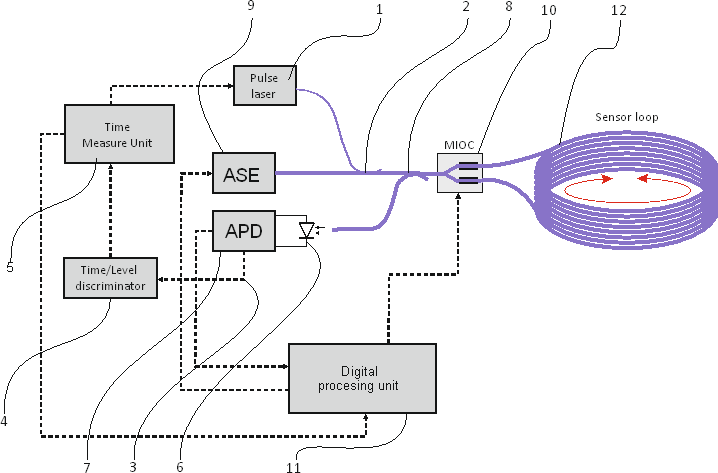
The circuit works on the ToF principle, measuring ToF of a short (100–500 s) pulse from an additional laser through a loop. At the output of the discriminator (after the time resulting from the length of the optical path), two pulses will be obtained with a spacing resulting from the current angular velocity of the system. The average of the measured ToFs of these pulses is directly proportional to the optical path of the system at the measured moment.
Due to the use of a coupler, the optical power from the ASE broadband source will be reduced. This requires the use of an appropriate source with sufficient output power. A typical telecommunications fibre-optic transmitter for a 1550 m band with a power of 2–4 mW was used as a pulsed laser. These transmitters are commonly used in telecommu-nications networks over distances of 40–80 km.
The main advantages of the above proposal are: the optical path measurement is evaluated in real time and no interruptions in the measurement of angular velocity are required, simple measurement system, low cost of getting a coupler, high speed. However, the disadvantages are: less optical power delivered to the measurement system by a broadband source, additional elements in the optical system.
Use of an additional pulsed laser with an optical switch
Such a system uses an additional laser for a 1550 nm band – identical to the ASE main continuous source. The additional laser is pulse-controlled, generating optical pulses with a power of about 2–4 mW. These pulses are intro-duced into the optical fibre using an additional MEMS-type optical switch. The switch changes the source of the optical signal sent to the measurement loop. The system is dedicated to rotational seismographs with remarkably high sensitivity associated with a long measurement loop (5000–10 000 m). The diagram of the measurement system is shown below in Fig. 3.
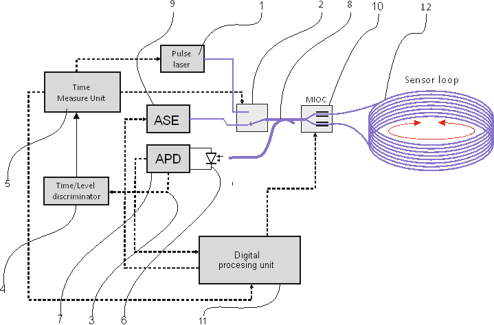
The system operates in the same manner as the previous example, utilizing the ToF principle to measure the ToF of a short (100–500 ns) pulse from an additional laser through a loop. At the output of the discriminator, (after the time resulting from the length of the optical path) two pulses will be obtained with a spacing resulting from the current angular velocity of the system. The average of the measured ToFs of these pulses is directly proportional to the optical path of the system at the measured moment.
The system requires periodic interruption of angular velocity measurements to measure the optical path. In sensor systems, such as rotational seismographs, pauses in measurements of no more than several dozen milliseconds are possible. They do not cause a significant reduction in the use value of measurements. The measurement capabili-ties are similar to those of the previous system and do not require re-description.
The main advantages of the above system are: low switch input losses into the optics and a simple measure-ment system. Whereas the disadvantages are: need to take a break in angular velocity measurements, higher imple-mentation cost compared to the use of a coupler, insertion of an additional element into the optical measuring system.
Application of the phase modulator as a measuring pulse generator
In the FOG system, utilizing the “closed-loop” technique, a MIOC phase modulator is employed which enables differential modulation of the phase of light supplied from a broadband source to the two opposite ends of the fibre-optic loop. Phase changes cause interference and the possibility of detecting intensity changes in the photodiode resulting from the phase difference. [1, 6, 10].
Most often, ramp-shaped signals are used to control MIOC in some solutions. The technique of alternating changes of decreasing amplitude (rectangular wave with variable amplitude) is used [18].
Introducing an additional cycle with a significant phase difference into the measurement algorithm, considering the last measured angular velocity, will enable the detection of such a pulse in the signal received by the photodiode. Appropriate electronic circuits enable the separation of this signal from the signal of the receiving system and its transmission to the ToF timing system. The diagram of such a solution is presented below in Fig. 4.

Experimental setup
This experiment investigates the variability of the optical path within a fundamental FOG under differing tempera-ture conditions and gradients across the fibre loop.
The initial experiments employed a straightforward setup that included a telecommunication pulsed laser, 5000 m of a single-mode fibre wound on a spool and a telecommunication pulse detector. An arbitrary waveform generator produced precise 20 ms pulses, while an HM8123 meter measured the delay caused by the fibre loop. Both devices were synchronized using a stable 10 MHz oven-controlled crystal oscillator (OCXO) generator. During the experiment, the fibre loop was gradually heated from 0 °C to 50 °C. For each temperature step, the average result from 100 measurements was recorded and is presented in Fig. 5.

The target experimental setup consists of the following components, as shown in Fig. 6.

The experiment entails applying controlled temperature changes and gradients using the heater to observe their effects on the optical path length within the fibre loop. By analysing the interference patterns detected by the photo-diodes, variations in phase shifts induced by thermal expansion or birefringence in the fibre can be quantified. This enables a more comprehensive understanding of how temperature fluctuations affect FOG performance, particu-larly in terms of stability and accuracy. During the experiment, the transit times of optical pulses through the loop and their temperature dependence will be measured. The results obtained will be utilized to develop compen-sation algorithms.
The experiment will be conducted using a closed-loop basic circuit, similar to those described in [4, 18, 19]. The setup includes a MIOC control circuit with a digital ramp, an autonomous microcontroller, and two 20-bit DAC converters configured in a differential circuit. It also features a measuring circuit with an APD diode, an automatic bias voltage regulation circuit for the photo-diode, and a 20-bit ADC converter with a sampling rate of 1 Msps [20]. The APD amplifier circuit is equipped with a built-in fast comparator for detecting spikes [1] that occur in the output signal after phase compensation. Additionally, the reference level is set using an extra DAC converter which is managed by a local feedback loop. A simple TDC7201 circuit was used to measure the total transfer time. It allows measuring the time between start/stop pulses in the range of 0.25 ns to 8 ms with a resolution of 55 ps (standard deviation 35 ps). It requires only a few additional components and an external, accurate 10 MHz reference, e.g., OCXO. Overall, the circuit is controlled by an external microcomputer based on the Raspberry Pi 5.
Conclusions
The research on compensating slow-drifting errors in FOGs highlights the potential of DOPM techniques. These methods leverage the ToF principle to enhance the accuracy of FOG systems, particularly in environments where tem-perature variations significantly impact the performance.
Three architectures – using an optical coupler, a MEMS optical switch, and an additional MIOC control – have been proposed, each with its advantages and limitations. The MIOC-based solution is considered the most promising due to its minimal disruption to existing systems.
Experimental studies are still in progress, but initial results indicate that it is possible to improve the accuracy of measurements in FOG even with low-cost measurement systems. By making the photodiode detection system slightly more complex, it becomes possible to generate pulses that measure the total optical path. Furthermore, with suitable modifications to the closed-loop algorithms, it should be possible to partially compensate for the effects of environ-mental conditions on angular velocity measurements.
Future Works
To further develop these methods, several areas require attention:
- Integration with Advanced Signal Processing Tech-niques: incorporating machine learning models, such as LSTM-RNN, can improve drift compensation by predicting and adjusting for temperature-induced changes in real time. This integration can enhance the robustness of FOG systems in dynamic environments.
- Comprehensive Temperature Modelling: developing more sophisticated temperature compensation models that account for both temperature and temperature change rates can significantly enhance the stability of FOG outputs. These models should be validated across a wide range of environmental conditions.
- Miniaturization and Manufacturing Advances: as FOGs become more integrated into compact systems, advancements in miniaturization and automated manufacturing processes will be essential for maintaining performance while reducing size and cost.
- Noise Reduction Strategies: implementing noise reduc-tion techniques, such as those used in rotational seismometers, can further improve the precision of FOG-based systems. This includes identifying and miti-gating sources of noise through device configuration adjustments.
- Adaptive Compensation Algorithms: developing adap-tive algorithms that can adjust compensation parameters based on real-time environmental conditions will enhance the adaptability of FOG systems in diverse applications
By addressing these areas, future research can lead to more accurate, reliable, and versatile FOG systems capable of operating effectively across various environmental conditions.
Authors’ statement
Article preparation, including the conceptualization and design of the electronic construction, as well as defining its operational principles, J.K.K. Contribution to the develop-ment of the electronic construction and overseeing the setup and execution of testing procedures, M.C.
References
-
Lefèvre, H. C. The Fiber-Optic Gyroscope, Second Edition. (Artech House, Boston, 2014).
-
Jaroszewicz, L. R. et al. FOSREM – Fibre-Optic System for Rotational Events & Phenomena Monitoring Project WebAge https://fosrem.eu/?page_id=807 (access: 2025.04.13).
-
Lefèvre, H. C. The fiber-optic gyroscope: Challenges to become the ultimate rotation-sensing technology. Opt. Fiber Technol. 19 , 828– 832 (2023).https://doi.org/10.1016/j.yofte.2013.08.007
-
Zając, P., Amrozik, P., Kiełbik, R., Maj, C. & Szerm, M. Self-noise reduction in a FOG-based rotational seismometer confirmed by Allan variance analysis. Opto-Electron. Rev. 4 , e152766 (2024) https://doi.org/10.24425/opelre.2024.152766
-
Кorkishko, Y. N. et al. Interferometric closed-loop fiber-optic gyroscopes. Proc. SPIE 8351 , 83513L-8 (2012). https://doi.org/10.1117/12.912937
-
Korkishko, Y. N. et al. High-Precision Fiber Optical Gyro with Extended Dynamical Range. in 2014 DGON Inertial Sensors and Systems (ISS) 1–14 (IEEE, 2014). https://doi.org/10.1109/InertialSensors.2014.7049410
-
He, M. et al. The space cold atom interferometer for testing the equivalence principle in the China Space Station. NPJ Microgravity 9 , 58 (2023). https://doi.org/10.1038/s41526-023-00306-y
-
Temperature Drift and Compensation Method of FOG Gyro ERICCO https://www.ericcointernational.com/application/temperature-drift-and-compensation-method-of-fog-gyro.html (access: 2025.04.13).
-
Li, Y. et al. Thermal phase noise in giant interferometric fiber optic gyroscopes. Opt. Express 27 , 14121–14132 (2019). https://doi.org/10.1364/OE.27.014121
-
Jaroszewicz, J. R. et al. Review of the usefulness of various rotational seismometers with laboratory results of fibre-optic ones tested for engineering applications. Sensors 16, 2161 (2016) https://doi.org/10.3390/s16122161
-
Kurzych, A. et al. Fibre-optic Sagnac interferometer in a FOG minimum configuration as instrumental challenge for rotational seismology. J. Light. Technol. 36, 879–884 (2018). https://doi.org/10.1109/JLT.2017.2769136
-
Кorkishko, Y. N. et al. Interferometric сlosed-loop fiber-optic gyroscopes. Proc. SPIE 8351, 83513L (2012). https://doi.org/10.1117/12.912937
-
TIE-19 Temperature Coefficient of the Refractive Index SCHOTT https://www.schott.com/shop/medias/schott-tie-19-temperature-coefficient-of-refractive-index-eng.pdf (acccess: 2025.04.13).
-
ToF: Time-of-Flight – Overview, Principles, Advantages AVSYSTEM (access: 2025-04-13) https://avsystem.com/blog/linkyfi/time-of-flight
-
LIDAR, Optical Distance & Time of Flight Sensors >AMS OSRAM https://ams-osram.com/innovation/technology/depth-and-3d-sensing/lidar-optical-distance-and-time-of-flight-sensors (access: 2024.04.13).
-
Understanding Time of Flight Systems: TOF, iTOF, and dTOF Lumispot Photoelectric Science & Technology Co. Ltd https://www.lumimetric.com/en/new/TOF-time-of-flight-definition-and-principle.html(access: 2025.04.13).
-
Kurzych, A. T., Jaroszewicz L. R., Dudek, M., Sakowicz, B. & Kowalski, J. K. Towards uniformity of rotational events recording – initial data from common test engaging more than 40 sensors including a wide number of fiber-optic rotational seismometers. Opto-electron. Rev., 29, 39–44 (2021). https://doi.org/10.24425/opelre.2021.135827
-
Jaroszewicz, L. R. et al. The fiber-optic rotational seismograph – laboratory tests and field application. Sensors 19, 2699 (2019). https://doi.org/10.3390/s19122699
-
Skalský, M., Havránek, Z. & Fialka, J. Efficient modulation and processing method for closed-loop fiber optic gyroscope with piezoelectric modulator. Sensors 19, 1710 (2019). https://doi.org/10.3390/s19071710
-
Niespodziany, S., Kurzych, A. T. & Dudek, M. Detector diode circuit noise measurement and power supply method selection for the fiber optic seismograph. Opto-Electron. Rev. 29, 71–79 (2021). https://doi.org/10.24425/opelre.2021.135830