This paper presents a study of gel electrolyte properties that may be applied in electrochromic devices. This research aimed to develop a stable and conductive gel electrolyte capable of dynamically changing light transmission in response to an applied voltage. The tested gels were prepared based on hydroxyethylcellulose, sodium alginate, xanthan gum, sorbitol, glycerol, and conductive salt LiClO4. During the research, the physicochemical properties of the gels were analysed, including mass change, density, ionic conductivity, and resistance. The optical quality of the gels was evaluated based on light transmission measurements. The conducted tests allowed for the selection of an optically homogeneous, transparent soft gel, free from air bubbles and contaminants. The highest ionic conductivity value obtained was 32.7 mS/cm2. The transparency changes observed in the constructed electrochromic device, depending on the type of gel, were from 55% to 90%.
Introduction
Electrochromic devices (ECDs) encompass a range of technological solutions that exploit the ability of materials to change their transparency (and sometimes colour) in response to an applied electric field [1]. ECDs are a vital component of modern technology, offering new opportu-nities for industrial applications and everyday life. They are used, among other things, in the production of smart windows [2, 3], displays [4–6], sensors [7, 8], anti-glare rear view mirrors [9], energy storage devices [10, 11], flexible electronics [12, 13], and smart fabrics [14, 15]. ECDs are also a key element of the future, significantly contributing to energy savings, improved quality of life, and safety.
ECDs are constructed as multilayer structures, which typically consist of transparent electrode layers [typically indium tin oxide (ITO) or fluorine-doped tin oxide (FTO)], an electrochromic layer (e.g., WO3), an electrolyte layer, and an opposite electrode layer [16–18]. The electrolyte serves as the medium that facilitates the transport of ions between the electrochromic layer and the electrode, while also acting as a barrier to electron flow [19, 20]. Properties of the electrolyte are crucial for achieving efficient performance of the ECD. Generally, liquid and solid electrolytes are distinguished [21, 22]. Liquid electrolytes were the first to be used in the construction of ECDs. Their main advantage is their high ionic conductivity (>10-3 S/cm), which enables the fast and efficient transport of ions between the electrodes, their functionality over a wide temperature range, and the ease with which their composition can be modified [23]. However, their disadvantages include low chemical stability and frequent leakage, which contribute to device damage and environmental pollution. Moreover, the solvents used in liquid electrolytes are often toxic and flammable (organic solvents) and may react with the electrodes, causing corrosion [23, 24]. To eliminate the risk of electrolyte leakage, next-generation ECDs are manufactured using fully solid systems. Solid electrolytes are less toxic, non-flammable, and may be flexible, providing better mechanical stability for the device. The greatest challenge for scientists is to overcome the low ionic conductivity of these materials compared to liquid electrolytes [23, 25]. Achieving an ionic conductivity similar to that of liquids would be a significant step forward, enabling further technological advancements. Gel electrolytes can meet this requirement based on natural polymers, which offer a unique combination of properties of both liquids and solids. The combination of cohesive properties typical of solids and diffusion characteristics of liquids makes gel electrolytes stand out for EC applications [26].
Due to their numerous advantages, including biodegradability, good physical and chemical properties, gel electrolytes made from natural polymers are among the most promising ion carriers. They are easily accessible and inexpensive, derived from products found in nature, such as plant cell walls, animal bones, and scales [23, 27].
So far, natural polymer matrices used in ECDs include cellulose and its derivatives [28], starches [29], chitosan [30], gelatine [31, 32], agar [33, 34]. Electrolytes based on natural polymers consist of a polymer matrix, liquid solvents (plasticizers), lithium salts, and additives (inorganic fillers). It has been found that blending polymers increases the sites for complexation, enhancing flexibility and amorphousness [35]. The use of plasticizers, depending on their viscosity and dielectric constant, significantly improves the ionic conductivity of the electrolyte. The most commonly used plasticizer is glycerol [36].
Good ionic conductivity, flexibility, and safety make gel electrolytes ideal for modern and innovative ECDs.
This paper discusses the preparation method of gel electrolytes based on selected organic materials and presents the results for a chosen gel, considered the most promising for use in ECDs.
Experimental
Selecting a template
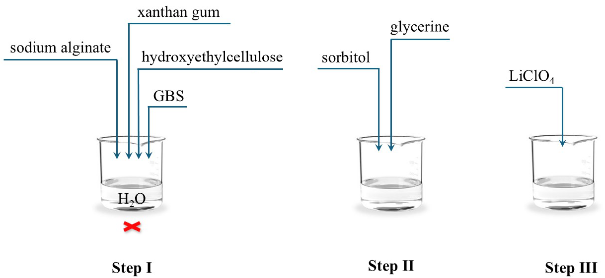
Fig. 1 presents a schematic diagram of the steps involved in preparing the hydroxyethylcellulose (HEC), sodium alginate, and xanthan gum-based gel electrolyte.
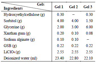
In the first step of a gel preparation, HEC was weighed and gradually added to deionized water, stirring at room temperature until a uniform consistency was achieved. The next step involved adding xanthan gum, which increased the viscosity of the mixture, facilitating the formation of a stable gel structure. The mixture was heated to 40 °C and stirred for 1.5 h to enhance the dissolution of the components. Subsequently, sodium alginate (400–600 cP) and GBS (an eco-friendly powder preservative composed of 70–80% glucono delta-lactone, 22–88% sodium benzoate, and a maximum of 1% water) were added, and the mixture was stirred for additional 45 min. In the next stage, sorbitol and glycerine were added as plasticizers to increase the flexibility and mechanical stability of the gel. Mixing continued for 20 min to ensure the complete dissolution of the components. In the final preparation stage, LiClO₄ was added to the mixture as an ion carrier.
The entire mixture was stirred for two hours. The gel was then subjected to ultrasonic treatment to remove air bubbles, which could affect its conductive and optical properties. Table 1 presents the compositions of the prepared gel electrolytes. The gels were stored at room temperature in sealed containers.
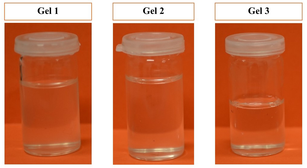
Fig. 2.Photos of the prepared gel electrolyte samples.
Homogeneous, transparent, soft gels were obtained, free from air bubbles and impurities (Fig. 2). During a 30 day period of visual observation, no discoloration, phase separation, or other structural changes were observed.
Research methodology
The gel density was determined using Archimedes’ method. A conical flask with a known volume was filled with gel at room temperature (20 °C) [37]. The density was calculated based on a difference in mass between the flask with the sample and the empty flask, as well as the known volume of the flask, according to the formula:
The stability of the gel was tested by weighing the samples at different time intervals: immediately after preparation, after one day, ten days, and thirty days. Measurements were carried out using a RADWAG AS220/C/2 balance with an accuracy of 0.001 g.
The conductivity and resistance of the gel were measured using an S230 conductivity meter equipped with an InLab731-ISM electrode. The accuracy of the S230 conductivity meter in conductivity measurements is ± 0.5% of the estimated value. The device includes automatic temperature compensation (ATC) for the electrode.
The EC system used in the study consisted of several layers:
To fabricate the EC structure, amorphous silica (SiO0) substrates with a transparent conductive ITO electrode (supplier: ITL) were used. The electrochromic WO3 layer was deposited onto the ITO-coated substrates through a mask using the electron beam evaporation method. The source material was WO3 granules (1–3 mm, 99.99%, supplier: Lesker), placed in a molybdenum crucible. The deposition process was carried out in a vacuum chamber evacuated to a base pressure of 2.5 · 10-5 mbar. The layer was deposited on substrates positioned 55 cm from the source and heated to a temperature of 80 °C. The electron beam current was set to 20 mA, and the accelerating voltage to 6 kV, allowing for a deposition rate of approximately 1.5 nm/s. During deposition, oxygen gas (99.999%) was introduced into the working chamber at a flow rate of 100 sccm, maintaining the chamber pressure at approximately 2.66 · 10-3 mbar. The thickness of the deposited layer was monitored in situ using a quartz crystal microbalance and was 285 nm.
Additionally, a Cr-Au layer (80 nm) was deposited onto the surface of the EC layer through a metal mask using the evaporation method. This layer served as an electrode, enabling the flow of electric current within the system.
These layers together form a structure capable of dynamically changing its optical properties under the influence of an applied electric voltage. A schematic diagram and a view of the studied EC structure are presented in Fig. 3.
The optical characteristics of the ECD were studied by measuring transmittance in the wavelength range of 250 to 1000 nm. The balanced tungsten-halogen light source (OceanOptics DH-2000-BAL) and a spectrophotometer (OceanOptics HR2000+) were used for optical transmittance measurements. Light was guided through a 600 μm optical fibre (QP600-1-SR-BX) to a collimating lens (OceanOptics 74-UV) positioned approximately 20 mm from the sample, providing uniform, perpendicular illumination with a spot diameter of ~3 mm. Transmitted light was directed to the spectrophotometer using a second collimating lens and optical fibre. The integration time was set to 100 ms, and each measurement was averaged over 10 scans. Data acquisition was performed using a SpectraSuite software (OceanOptics).
The optical contrast of the electrochromic material is determined by the modulation of transmittance (ΔT) [37, 38]:
\(
\Delta T=T_{\mathrm{b}}-T_{\mathrm{c}}
\) (2)
where Tb is the transmittance in the bleached state, and Tc is the transmittance in the coloured state.
The optical density (OD) was calculated using the formula [35, 39]:
Fig. 4 presents an SEM image of the WO3 electro-chromic layer. The surface of the thin-film coating appeared porous, with numerous cracks and voids visible between the grains. The grain size on the surface of the layer ranged from 50 nm to 100 nm. In contrast, the cross-section of this sample exhibited a fibrous structure.
Fig. 4.SEM image of the cross-section and surface of the
fabricated WO3.
Characterization of gel electrolyte properties
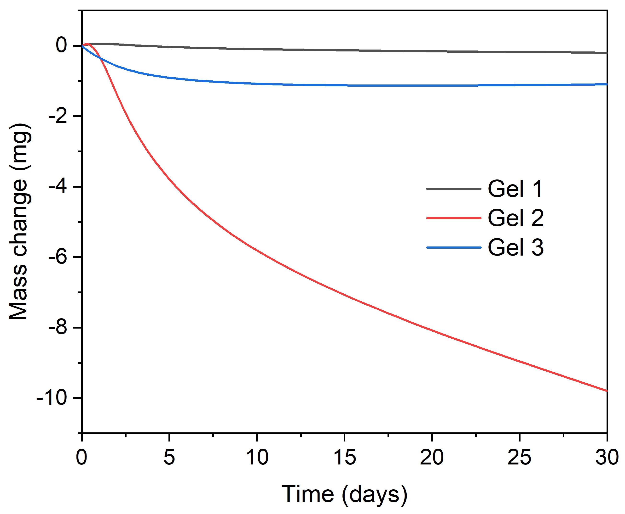
The studied gels differed in density. Gel 1 had the lowest density of 0.996 g/cm³, gel 2 had a density of 1.042 g/cm³, and gel 3 reached the highest value, equal to 1.370 g/cm³. Fig. 5 presents the mass change (Δm) of the three studied EC gels over time, expressed in milligrams relative to the initial value (day 0). The analysis of the graph indicates that gel 2 exhibits the most significant mass loss over the 30 day period, which may suggest lower stability. In the case of gel 3, an initial mass decrease is observed, which subsequently stabilizes, indicating partial equilibrium of the system. Gel 1 shows the most minor variation throughout the observation period, confirming its high resistance to mass loss and good long-term stability.
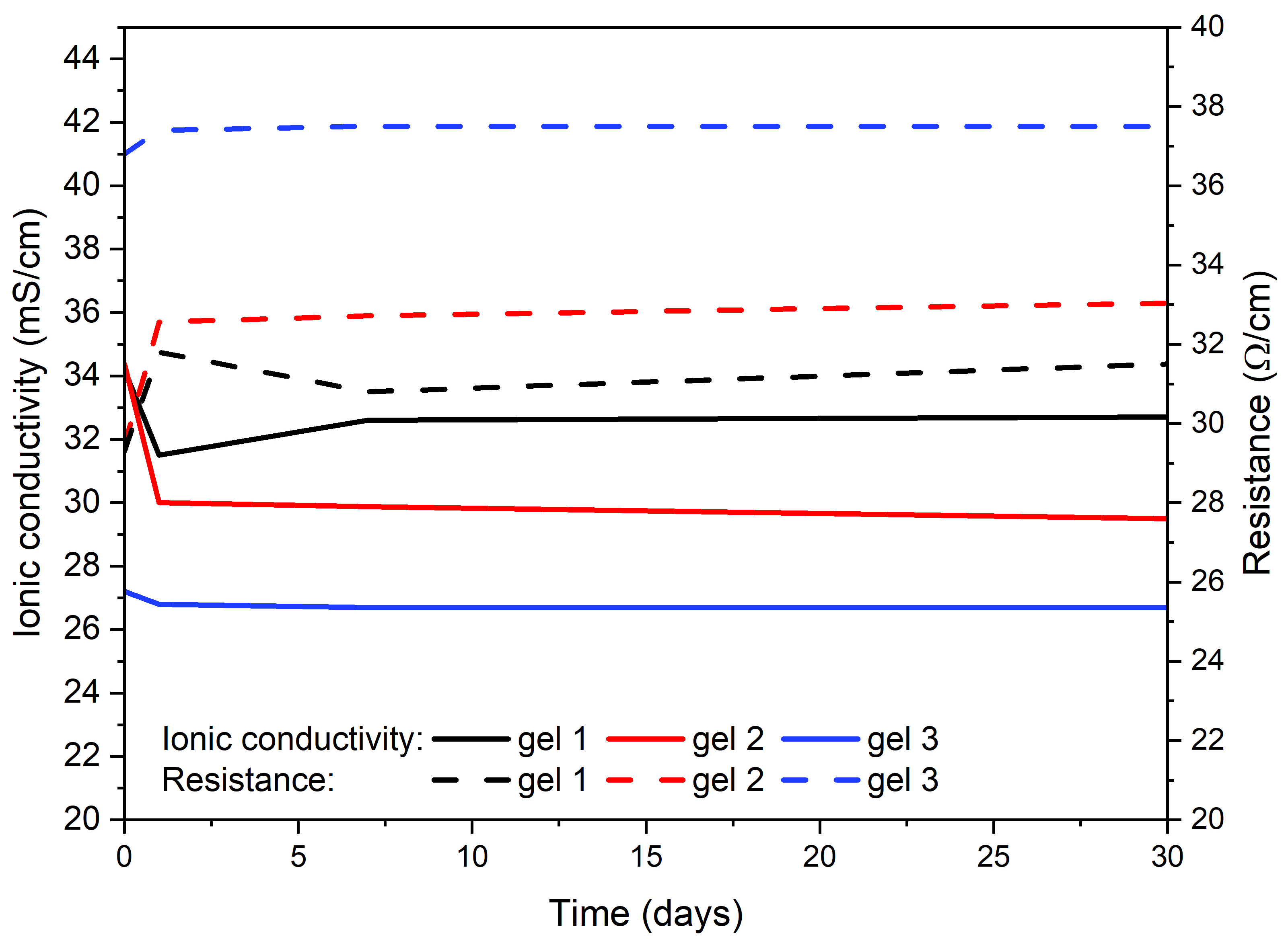
For most gels, ionic conductivity decreases after the first day. Then it stabilizes (Fig. 6). This behaviour may be related to the stabilization of the gel structure or processes associated with gelation. Comparing the values after one, seven, and thirty days, gel 3 demonstrates the highest stability, with minimal changes in ionic conductivity, maintaining 26.7 mS/cm after thirty days. In the case of gel 1, a slight decrease in ionic conductivity is observed after the first day, after which the value stabilizes at approximately 32.7 mS/cm. Gel 2 exhibits a gradual reduc-tion in ionic conductivity over time, reaching 29.8 mS/cm after thirty days. For all gels, the resistance value is inversely proportional to ionic conductivity.
Fig. 6.Ionic conductivity and resistance of various gels over
time.
Characterization of ECD properties
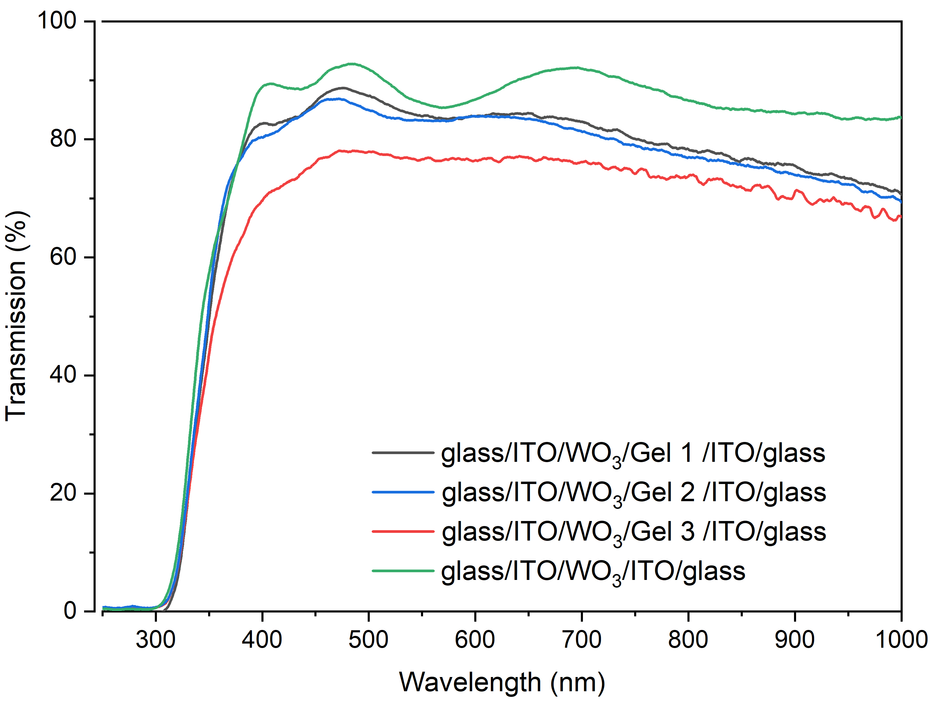
In the first stage of the measurements, the transmittance of the glass/ITO/WO3/ITO/glass structure was determined. Subsequently, the glass/ITO/WO3/gel electrolyte/ITO/ glass structures were studied within the spectral range of approximately 250 nm to 1000 nm (Fig. 7).
Fig. 7.Transmission characteristics of EC structures.
The reference structure glass/ITO/WO₃/ITO/glass, without gel, exhibits the highest transmittance across the entire wavelength range. The addition of gels reduces the transmittance of the systems. Gels 1 and 2, compared to gel 3, show similar transmittance characteristics across the entire range. This result is consistent with previous data, where gels 1 and 2 demonstrated higher ionic conductivity than gel 3. Gel 3 is characterized by the lowest transmit-tance, which may be related to its high glycerine content, affecting the viscosity of the tested gel.
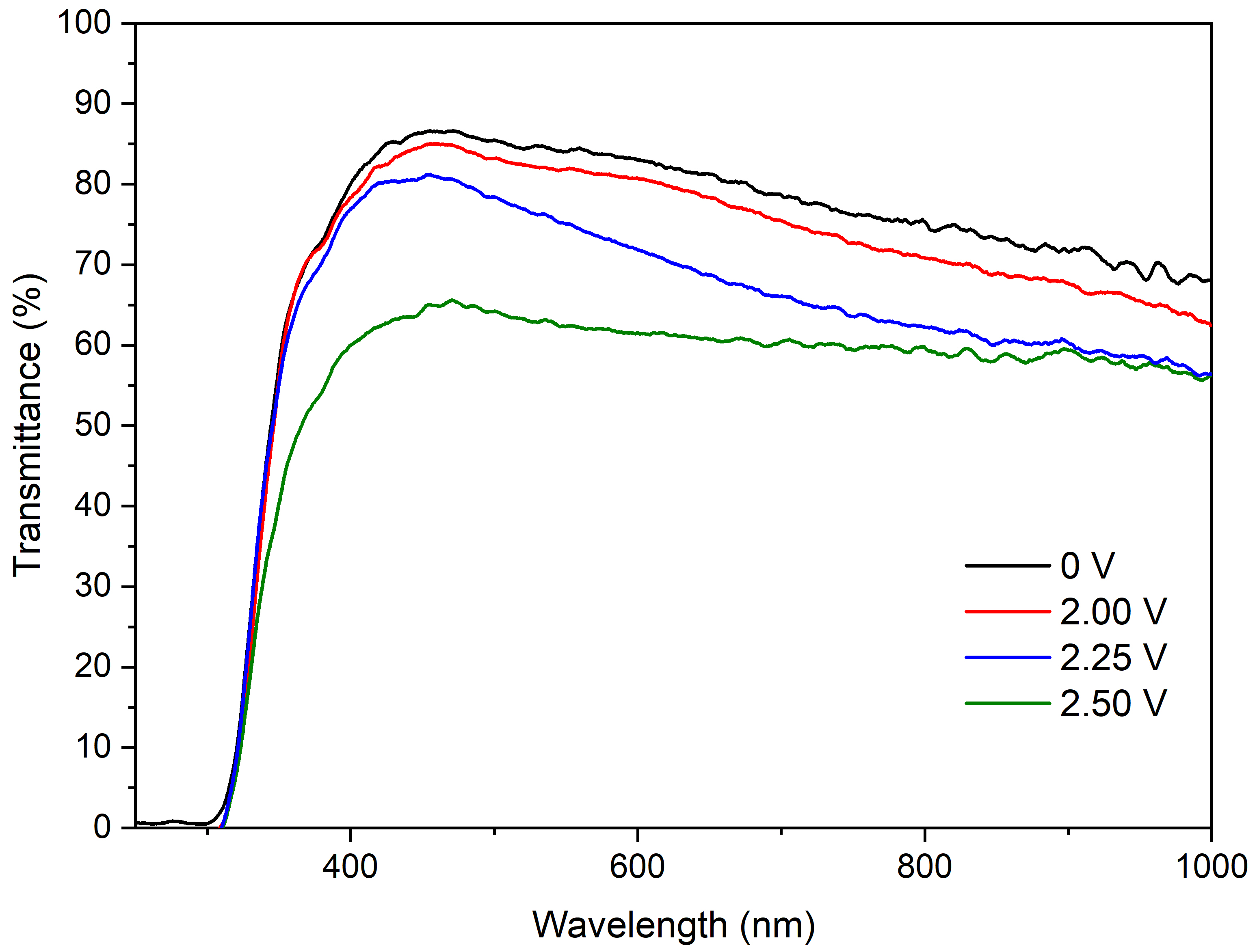
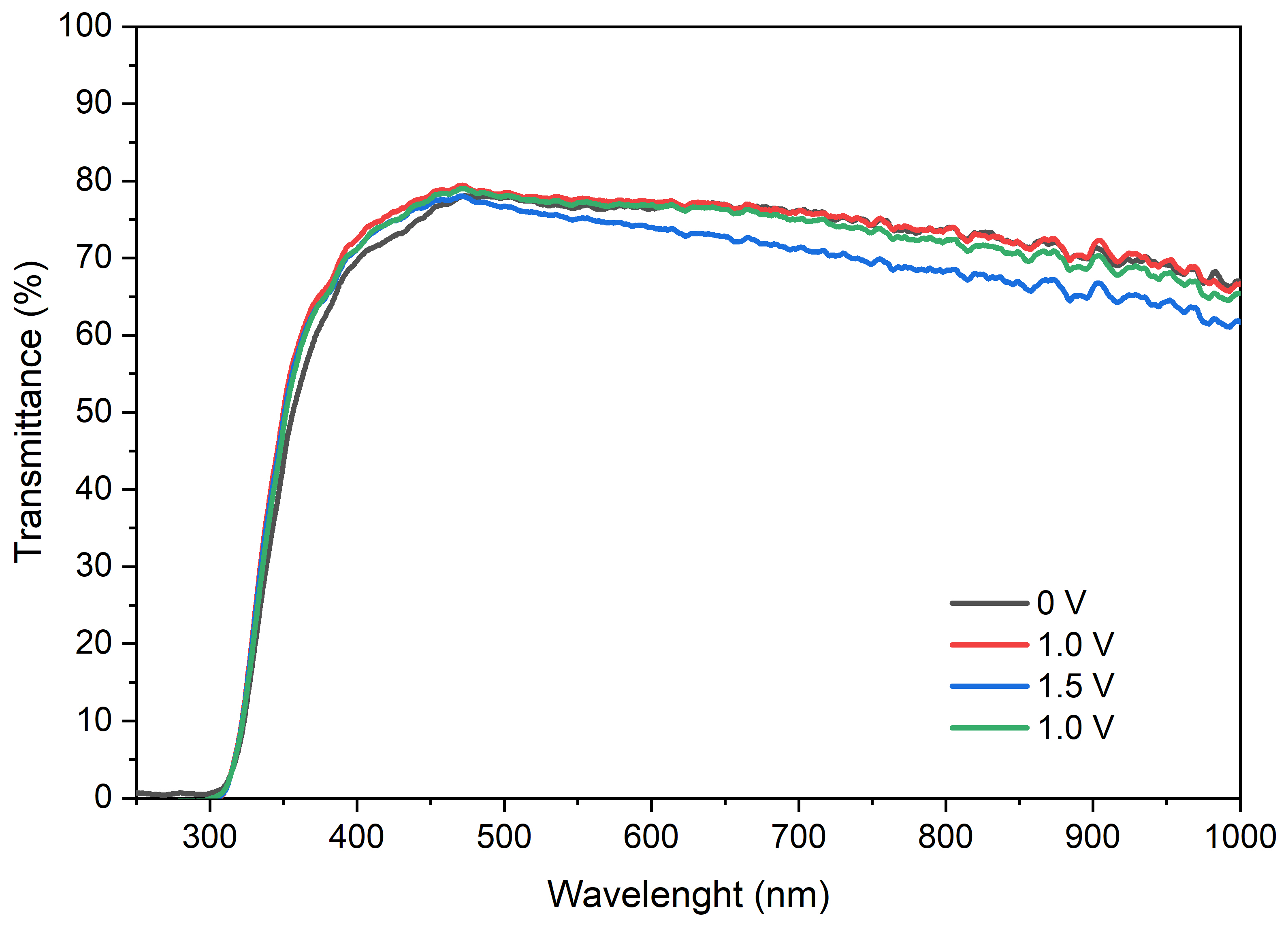
Subsequently, the studied structures were polarized using a DC voltage to induce the EC process, during which the material altered its optical properties. Figures 8–10 show the light transmission characteristics for the structures with the tested gels. Based on the analysis, differences in their optical properties and responses to the applied voltage can be observed. The structure with gel 1 exhibits the highest sensitivity to voltage changes (Fig. 8). The transmittance value decreases with increasing voltage. The highest transmittance is observed at 0 V, while the lowest is at 2.50 V. Gel 2 (Fig. 9) demonstrates a more negligible influence of voltage on transmission compared to gel 1. Although transmission changes are observed in the wavelength range of 500 to 1000 nm, these differences are relatively minor. Transmission remains pretty stable and consistent across the entire analysed voltage range (0 V to 1.5 V). Gel 3 (Fig. 10) is characterized by a more uniform transmission than gel 2. The differences between transmission at 0 V and higher voltages (up to 1.5 V) are practically negligible. The plots indicate that this gel shows minimal responsiveness to voltage changes.
Fig. 10.Transmission characteristics of the EC structure for gel 3.
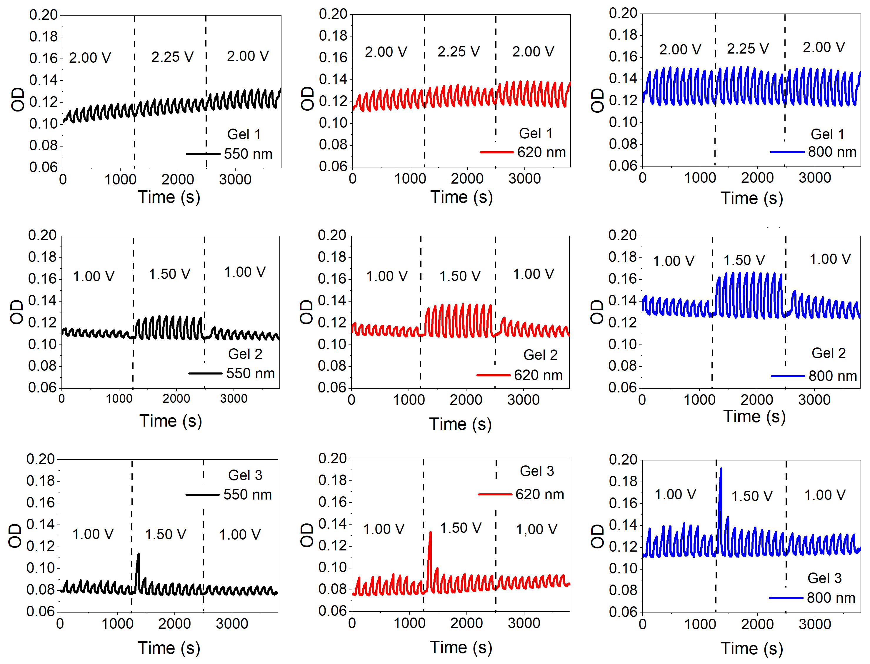
To determine the dynamics of the darkening and bleaching processes, measurements were conducted as a function of time for three wavelengths: 550 nm, 620 nm, and 800 nm. The selection of these wavelengths allowed for a comprehensive study of the material optical properties within the visible light range (550 nm, 620 nm) and the near-infrared (NIR) range (800 nm). Three wavelengths were selected for optical studies to address different aspects of the EC behaviour: 550 nm is commonly used to track colouration, as the reduced form of WO₃ absorbs strongly in this range; 620 nm helps detect optical effects-related to material imperfections; and 800 nm, in the NIR region, provides insight into the role of free charge carriers and thermal modulation by the gel. For each selected wave-length, transmittance changes were recorded at regular time intervals during both the colouring and bleaching processes. The results for the three tested structures are presented in Figs. 11–13.
Fig. 13.Transmission characteristics of gel 3 for three
wavelengths: 550 nm, 620 nm, and 800 nm.
Gel 1 was tested over a wider voltage range because it exhibited higher ionic conductivity and greater EC stability compared to gels 2 and 3. This allowed for safe switching at higher voltages without signs of WO3 layer degradation or undesirable side effects. For gel 1 (Fig. 11), as the voltage increases, changes in transmittance values are observed for different wavelengths. At lower voltages, transmittance remains relatively stable for each wavelength, whereas at higher voltages, pronounced oscillations occur, indicating a stronger electrolyte response to voltage changes. For the 800 nm wavelength, the most significant difference between the coloured and bleached states is about 16 percentage points, suggesting that the EC effect is most pronounced at this wavelength. For gel 2 (Fig. 12), at a voltage of 1.0 V, transmittance for all wavelengths (550 nm, 620 nm, 800 nm) remains stable. While the curves for each wavelength differ, the changes are regular and slight. Wavelengths of 550 nm and 620 nm exhibit less abrupt variations in transmittance, maintaining more stable behaviour as voltage increases. For 800 nm, transmittance fluctuates between approximately 68% and 74%, a difference of about 6 percentage points. The material exhibits greater sensitivity to an applied voltage of 1.5 V compared to shorter wavelengths (550 nm and 620 nm). At 1.5 V, transmittance modulation remains most pronounced for the 800 nm wavelength (approximately 6 percentage points), while for the shorter wavelengths it is about 2–3 percentage points. This indicates that the 800 nm wavelength is the most responsive to material changes under applied voltage. For gel 3 (Fig. 13), at a voltage of 1.0 V, transmittance for the three wavelengths (550 nm, 620 nm, 800 nm) remains stable at approximately 85%. In the NIR range (800 nm), the material exhibits minor transmittance changes than for shorter wavelengths (550 nm, 620 nm), but the changes are still noticeable. The transmittance difference ranges from 4 to 6 percentage points, depending on the applied voltage.
The observed transmittance drift in Figs. 11–13 suggests progressive material fatigue, likely associated with partial irreversibility of ion exchange and structural changes in the WO3 layer.
The results of the study on the transmittance changes of the analysed EC structures are presented in Fig. 14 as optical density (OD) change characteristics, calculated according to (2). It can be observed that gel 3 exhibits less intense OD oscillations compared to gel 2. This suggests a more stable response to voltage, but simultaneously a lower optical modulation. The distinct peak observed immediately after a voltage switched to 1.5 V can be attributed to the overshoot phenomenon. It is related to the rapid adsorption of ions at the WO3 surface and delayed diffusion into the depth of the layer.
Fig. 14.Optical density characteristics of electrochromic structures.
Gel 2 shows a greater range of OD change over time, indicating higher electroactivity. In contrast, gel 1 presents more stable and less pronounced OD variations. Additionally, at a wavelength of 800 nm, OD oscillations are more pronounced than at 550 nm and 620 nm. This may result from differences in the optical mechanisms occurring in the studied gels.
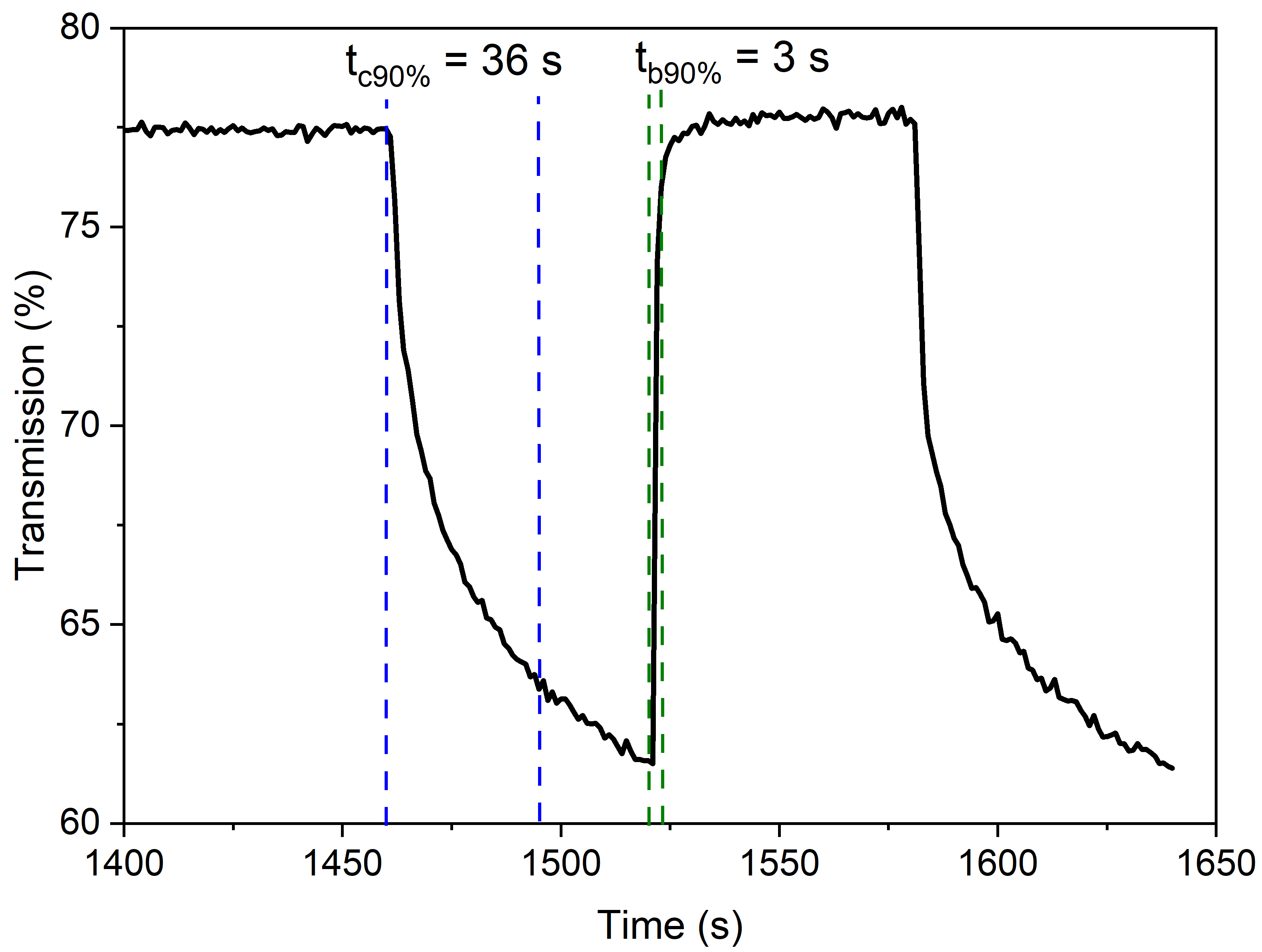
Fig. 15 presents an example of the transmittance (%) change over time (s) for the colouring and bleaching process of the structure with gel 1.
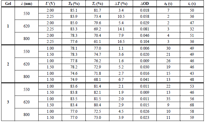
The initial transmittance value is approximately 78%, indicating a high level of light transmission in the bleached state. When the colouring process begins, transmittance starts to decrease, reaching 90% of the target minimum (defined as tc 90%) after 36 s, representing the time required for the material to colour to this level. In the bleaching phase, transmittance increases again, achieving 90% of the target maximum (tb90%) within 3 s, indicating that the bleaching process is significantly faster than the colouring process. The bleaching time is more efficient compared to the colouring time. These results are typical for electrochromic materials, where the bleaching (reduction) process usually occurs faster than colouring (oxidation) due to differences in ion diffusion mechanisms and changes in optical states [40]. The tb and tc times determined for the studied EC structures are listed in Table 2.
Fig. 15.Transmission vs. time curve at a wavelength of 800 nm,
obtained by applying a square wave voltage of −2.00 V
(colouration) and +2.00 V (bleaching) for the EC
structure with gel 1.
Based on the analysis of the results, it can be concluded that the structure with gel 1 exhibits the best EC properties compared to the other studied gels. It is characterized by the highest optical contrast (ΔT) and the most significant change in OD (ΔOD), particularly at 800 nm. Simultane-ously, the colouring time (tb) for gel 1 is relatively short, indicating good kinetics for the colouring reaction. Gels 2 and 3 exhibit lower optical contrast and longer bleaching times (tc), which may be attributed to slower ion diffusion within their matrices. These findings are consistent with the literature, which emphasizes that higher voltages enhance electrochromic performance and that bleaching time often exceeds colouring time due to differences in reaction mechanisms and diffusion processes [40]. Further optimi-zation of the gels, for example, through composition modifications, could improve their properties
Conclusions
The composition of gels significantly influences their density and electrical properties. Glycerine, as a substance with a high specific gravity, increases gel density and enhances ionic conductivity; however, excessive amounts can reduce ion mobility. Gel 3, containing the highest amount of glycerine (6.00 g), achieved the highest density (1.370 g/cm3) but the lowest ionic conductivity (approxi-mately 27 mS/cm) due to its high viscosity, which limits ion mobility. Gel 1, with a moderate amount of glycerine (2.00 g), exhibited the lowest density (0.996 g/cm3) and the highest ionic conductivity (approximately 32 mS/cm) because its low viscosity facilitated better ion mobility. Gel 2, with an intermediate amount of glycerine (3.00 g), had a medium density (1.042 g/cm³) and moderate ionic conductivity (approximately 30 mS/cm), reflecting a balance between viscosity and ion mobility. HEC, xanthan gum, and sodium alginate served as gelling and stabilizing agents, increasing gel viscosity but reducing ionic conductivity by limiting ion mobility. This effect was most pronounced in gel 3, where the highest viscosity led to restricted ionic conductivity. In contrast, the lower concentration of gelling agents in gel 1 enabled better ion flow, resulting in the highest conductivity.
The composition of the gels had a significant impact on their optical properties. Gel 1, containing HEC, xanthan gum, and alginate, showed the highest transmittance. Gel 2, lacking HEC and containing more glycerine, exhibited lower optical clarity. Gel 3, without alginate and with the highest glycerine content, had the lowest transmittance across the entire wavelength range. The increased amount of glycerine may have contributed to higher viscosity, light scattering, and absorption, which reduced the transparency of the gel. The excess glycerine leads to greater light absorption. LiClO4 salt, a constant component in all gels, ensures comparable ionic properties across the gels, but its impact on light transmittance depends on the other ingredients in the gel compositions.
The planned optimization of the gel composition will focus on increasing ionic conductivity and improving optical stability during repeated switching.
Authors’ statement
Research concept and design, U.W. and A.O.; collection and/or assembly of data, U.W.; data analysis and interpretation, U.W. and A.O.; writing the article, U.W.; critical revision of the article, A.O.; final approval of article, U.W. and A.O.
Acknowledgements
The authors wish to thank Prof. Jarosław Domaradzki, DSc, Eng. and Michał Mazur, PhD, DSc, Eng. from Wrocław University of Science and Technology for their assistance in preparing this publication.
This work was co-financed from the sources given by the Polish Ministry of Education and Science under subsidy for Department of Electronic and Photonic Metrology K31/W12N at Wrocław University of Science and Technology.
References
Abdulwahid, R. T., Aziz, S. B. & Kadir, M. F. Z. Replacing synthetic polymer electrolytes in energy storage with flexible biodegradable alternatives: sustainable green biopolymer blend electrolyte for supercapacitor device. Mater. Today Sustain. 23, 100472. (2023) https://doi.org/10.1016/j.mtsust.2023.100472
Alves, R. et al. Agar-based solid polymer electrolyte-containing ionic liquid for sustainable electrochromic devices. ACS Sustain. Chem. Eng. 11, 16575–16584 (2023).>https://doi.org/10.1021/acssuschemeng.3c04925
Du, Z., Wang, S., Gu, C. & Yang, G. Recent advances in photo‐ or electro‐chromic smart windows and their thermal regulation. Responsive Mater. 3, 0007 (2025). https://doi.org/10.1002/rpm.20250007
Avellaneda, C. O. et al. All solid-state electrochromic devices with gelatine-based electrolyte. Sol. Energy Mater. Sol. Cells 92, 228– 233 (2008). https://doi.org/10.1016/j.solmat.2007.02.025
Brzezicki, M. A systematic review of the most recent concepts in smart windows technologies with a focus on electrochromics.Sustainability 13, 9604 (2021). https://doi.org/10.3390/su13179604
Chen, L. et al. Unveiling dynamics evolution mechanism of electrochromic process in WO3-x film with thickness dependence. Electrochim. Acta 505, 144958 (2024). https://doi.org/10.1016/j.electacta.2024.144958
Costa, R. G. F., Avellaneda, C. O., Pawlicka, A., Heusing, S. & Aegerter, M. A. Optoelectrochemical characterization of electrochromic devices with starch based solid electrolytes. Mol. Cryst. Liq. Cryst. 447, 45/[363]–53/[371] (2006). https://doi.org/10.1080/15421400500380036
Eren, E. Li+ doped chitosan-based solid polymer electrolyte incorporated with PEDOT:PSS for electrochromic device. J. Turk. Chem. Soc. A: Chem. 5, 1413–1422 (2018). https://doi.org/10.18596/jotcsa.433901
Ernest, C., Fagour, S., Sallenave, X., Aubert, P. & Vidal, F. (2024). An electrochromic displays comprising the three primary cyan magenta and yellow colors under juxtaposed and stacked architectures. Adv. Mater. Technol. 9, 2301654 (2024). https://doi.org/10.1002/admt.202301654
Fu, G. et al. Highly integrated all-in-one electrochromic fabrics for unmanned environmental adaptive camouflage. J. Mat. Chem. A 12, 6351–6358 (2024). https://doi.org/10.1039/D3TA07562A
Gadgil, C., Ghosh, A., Bhattacharjee, A. & Praveen, P. L. Electrically powered active smart windows. Next Sustainability 3, 100027 (2024). https://doi.org/10.1016/j.nxsust.2024.100027
Ghazali, N. M. Studies on H+ ions conducting bio-polymer blend electrolyte based on alginate-PVA doped with NH4NO3. J. Non- Cryst. Solids 598, 121939 (2022). https://doi.org/10.1016/j.jnoncrysol.2022.121939
Girotto, E. M. & De Paoli, M.-A. Flexible electrochromic windows: A comparison using liquid and solid electrolytes. J. Braz. Chem. Soc. 10, 394–400 (1999). https://doi.org/10.1590/S0103-50531999000500010
Granqvist, C. G., Arvizu, M. A., Qu, H.-Y., Wen, R.-T. & Niklasson, G. A. Advances in electrochromic device technology: Multiple roads towards superior durability. Surf. Coat. Technol. 357, 619–625 (2019). https://doi.org/10.1016/j.surfcoat.2018.10.048
Gupta, J., Shaik, H., Gupta, V. K. & Sattar, S. A. Perspective of electrochromic double layer towards enrichment of electrochromism: A review. Braz. J. Phys. 54, 89 (2024). https://doi.org/10.1007/s13538-024-01463-5
Higginbotham, H. F.. Electrochemically synthesised xanthone- cored conjugated polymers as materials for electrochromic windows. Electrochim. Acta 273 264–272 (2018). https://doi.org/1 0.1016/j.electacta.2018.04.070
Ledwon, P., Andrade, J. R., Lapkowski, M. & Pawlicka, A. Hydroxypropyl cellulose-based gel electrolyte for electrochromic devices. Electrochim. Acta 159, 227–233 (2015). https://doi.org/10.1016/j.electacta.2015.01.168
Lee, H. J. et al. Electrochromic devices based on ultraviolet-cured poly(methyl methacrylate) gel electrolytes and their utilisation in smart window applications. J. Mater. Chem. C 8, 8747–8754 (2020). https://doi.org/10.1039/D0TC00420K
Li, L., Yu, Z., Ye, C. & Song, Y. Structural color boosted electrochromic devices: Strategies and applications. Adv. Funct. Mater. 34, 2311845 (2024). https://doi.org/10.1002/adfm.202311845
Li, M. et al. Preparation of WO3-based flexible electrochromic fabrics and their near infrared shielding application. J. Mater. Chem. C 12, 5420–5430 (2024). https://doi.org/10.1039/D4TC00403E
Ma, B. et al. Ionic gel electrolytes for electrochromic devices. ACS Appl. Mater. Interfaces 16, 48927–48936 (2024). https://doi.org/10.1021/acsami.4c11641
Manjakkal, L. et al. Multifunctional flexible and stretchable electrochromic energy storage devices. Prog. Mater. Sci. 142, 101244 (2024). https://doi.org/10.1016/j.pmatsci.2024.101244
Mutlu, E., Şenocak, A., Demirbaş, E., Koca, A. & Akyüz, D. Electrochromic molecular imprinted polymer sensor for detection of selective acetamiprid. Microchem. J. 196, 109626 (2024). https://doi.org/10.1016/j.microc.2023.109626
Pawlicka, A., Dragunski, D., Guimarães, K. & Avellaneda, C. Electrochromic devices with solid electrolytes based on natural polymers. Mol. Cryst. Liq. Cryst. 416, 105–112 (2004). https://doi.org/10.1080/15421400490482033
Qian, C., Wang, P., Guo, X., Jiang, C. & Liu, P. High-contrast energy-efficient flexible electrochromic devices based on viologen derivatives and their application in smart windows and electrochromic displayers. Sol. Energy Mater. Sol. Cells 266, 112669 (2024). https://doi.org/10.1016/j.solmat.2023.112669
Sare, H. & Dong, D. Electrochromic polymers: From electrodeposition to hybrid solid devices. Energies 17, 232 (2024). https://doi.org/10.3390/en17010232
Serra, J. P. et al. High-performance sustainable electrochromic devices based on carrageenan solid polymer electrolytes with ionic liquid. ACS Appl. Eng. Mater. 1, 1416–1425 (2023). https://doi.org/10.1021/acsaenm.3c00090
Taneja, N. et al. Advancements in liquid and solid electrolytes for their utilization in electrochemical systems. J. Energy Storage 56, 105950 (2022). https://doi.org/10.1016/j.est.2022.105950
Thakur, V. K., Ding, G., Ma, J., Lee, P. S. & Lu, X. Hybrid materials and polymer electrolytes for electrochromic device applications. Adv. Mater. 24, 4071–4096 (2012). https://doi.org/10.1002/adma.201200213
Vacareanu, L., Gavril, A.-I. & Damaceanu, M.-D. Smart polymer coatings electrogenerated from star-shaped oligomers bearing variable π-spacers with integrated electrochromic characteristics and sensing capability towards harmful nitroaromatic derivatives. Prog. Org. Coat. 189, 108328 (2024). https://doi.org/10.1016/j.porgcoat.2024.108328
Varshney, P. K. & Gupta, S. Natural polymer-based electrolytes for electrochemical devices: A review. Ionics 17, 479–483 (2011). https://doi.org/10.1007/s11581-011-0563-1
Wang, J., Wang, Z., Zhang, M., Huo, X. & Guo, M. Toward next‐ generation smart windows: An in‐depth analysis of dual‐band electrochromic materials and devices. Adv. Opt. Mater. 12, (2024). https://doi.org/10.1002/adom.202302344
Wang, M. et al. Carbon dots as multifunctional electrolyte additives toward multicolor and low self-discharge electrochromic energy storage devices. Energy Storage Mater. 65, 103110 (2024). https://doi.org/10.1016/j.ensm.2023.103110
Pullar, R.C. et al. High colouring efficiency, optical density and inserted charge in sol–gel derived electrochromic titania nanostructures. Energy Adv. 1, 321–330 (2022). https://doi.org/10.1039/d2ya00016d
Yang, J. et al. Intelligent EC rearview mirror: Enhancing driver safety with dynamic glare mitigation via cloud edge collaboration. (2024). https://doi.org/10.48550/arXiv.2405.05579