Performance evaluation of 6.4 Tbps WDM-MIMO FSO system employing QAM-FSK dual modulation in diverse atmospheric conditions
Seenivasan S*
Karpagarajesh G
Article Info
Received 16 Dec. 2025
Received in revised form 10 Feb. 2026
Accepted 16 Feb. 2026
Available on-line 24 Mar 2026
Keywords: FSO; WDM; SNR; BER; weather conditions.
Abstract
Free-space optics (FSO) is a promising technology for meeting the high bandwidth and data rate requirements of modern wireless communications. However, atmospheric instability, such as turbulence, significantly degrades the quality of the received signal. This challenge can be effectively mitigated by integrating wavelength-division multiplexing (WDM) and multiple-input multiple-output (MIMO) techniques. This research presents a simulation- based performance analysis of a quadrature amplitude modulation frequency-shift keying (QAM-FSK) dual-modulated, linearly polarised WDM-MIMO-FSO system under various atmospheric conditions, including haze, rain, and fog. The proposed system uses eight individual wavelength channels, each carrying 200 Gbps of QAM-FSK-modulated data, which are then transmitted via four FSO-MIMO links. This configuration achieves a high net data transmission rate of 6.4 Tbps. The simulation results show that under clear weather conditions, the system can achieve a remarkable link range of up to 113 km. Furthermore, across all eight wavelength channels and under various adverse atmospheric conditions, the proposed system demonstrates a superior Q-factor, high signal-to-noise ratio (SNR), and low bit error rate (BER) when compared to prior works in the literature.
1. Introduction
Optical wireless communication can be divided into indoor and outdoor systems. Outdoor optical wireless communication is also referred to as free-space optics (FSO) [1]. The FSO technique enables high-data rates when a clear line of sight exists between the transmitter and receiver [2–4]. The limited spectrum available to radio frequency systems cannot accommodate the rapid growth and increasing demand for wireless networks. This limitation can be addressed by adopting FSO communication. High bandwidth is now essential for fast data transmission, which can be achieved using wavelength division multiplexing (WDM) techniques [5].
WDM is employed in both fibre-optic and FSO systems to meet bandwidth requirements and ensure reliable communication under heavy internet traffic by leveraging advanced control technologies [6]. Implementing WDM increases data capacity [7, 8]. FSO systems combined with WDM can transmit data at gigabit per second (Gbps) rates in complex networking scenarios. Numerous studies have reported significant performance improvements in WDM‑based FSO communication [9].
WDM supports independent channels and enables transmission at terabit per second rates, making it a highly suitable technique for broadband communications [10, 11]. However, weather conditions such as haze, rain, and fog can severely affect data transmission quality in these communication links [12, 13]. These challenges can be mitigated by employing WDM, which offers duplex communication, increased capacity, and extensive coverage [14]. Additionally, multiple-input multiple-output (MIMO) architectures can further enhance link performance and reduce the impact of atmospheric conditions [7, 15]. Recent research has focused on evaluating the performance of WDM-based FSO communication links to enhance system data capacity. Singh et al. examined the impact of haze, rain, and fog on a dual-polarisation quadrature phase-shift keying (QPSK) system with 32 multiplexed WDM channels, achieving a total data rate of 6.4 Tbps and a spectral efficiency of 3.33 bits/s/Hz [16]. Sharma et al. investigated a 1280 Gbps fibre plus FSO hybrid system using 32 channels of dense wavelength division multiplexing (DWDM) under various modulation schemes, including modified duo-binary return-to-zero (MDRZ), compressed spectrum return-to-zero (CSRZ), and duo-binary return-to-zero (DRZ) [17].
Ben Khalifa et al. conducted a simulation study of an 80 Gbps orthogonal frequency division multiplexing (OFDM)-based optical fibre communication (OFC) link with WDM at two wavelengths and mode division multiplexing (MDM) using Hermite-Gaussian modes [18]. Kaur et al. reported on the performance of a terrestrial dual polarisation QPSK-MDM-WDM FSO link with a data rate of 1000 Gbps under both clear and adverse weather conditions [19]. Aly et al. proposed a 60 Gbps spectral amplitude coding optical code division multiple access (SAC-OCDMA) system combined with polarisation division multiplexing (PDM) and evaluated its performance under clear, hazy, rainy, and foggy conditions [20]. Yarra et al. analysed an 80 Gbps orbital angular momentum (OAM) system integrated with PDM-offset (O)QPSK for FSO transmission under clear, rain, fog, and dust scenarios [21].
This proposed work numerically evaluates the performance of a QAM-FSK modulated, linearly polarised, WDM-MIMO-based FSO system under various weather conditions, including haze, rain, and fog. The proposed system utilizes eight independent wavelength channels multiplexed using WDM. Each channel transmits 200 Gbps of data, dual-modulated by QAM-FSK, across four FSO-MIMO. The total transmission data rate achieved is 6.4 Tbps. System performance and observations are assessed using an Optisystem simulation software.
This research paper is organised as follows: the proposed FSO architecture, with explanations of the components and the impact of atmospheric turbulence, is reported in section 2. Section 3 briefs the simulation setup of the proposed work. Section 4 presents the simulation results for the proposed work across diverse weather conditions. Section 5 provides the conclusion of the work.
2. Proposed system
The transmitter block diagram of the proposed WDMMIMO-based FSO (8 × 4 × 200 Gbps) system is shown in Fig. 1. It comprises eight independent channels spanning 850–864 nm, each with a 200 Gbps data rate. The system net transmission rate is 6.4 Tbps. Pseudo-random bit sequence generators (PRBSG) generate the bits of data streams that are connected with each QAM and FSK modulators of individual channels in the transmitter block. In every channel, two QAM modulators and one FSK modulator are used to electrically modulate the bitstreams generated by PRBSG.
To increase the signal strength, the proposed system adapted a continuous wave laser measured (CWLM) as a light source with 10 dBm as a power and a dual-port dualdrive Mach-Zehnder modulator (DPDDMZM) as an optical modulator. DPDDMZM optically modulates the signal from QAM and FSK modulators. This modulated signal is linearly polarised by a linear polariser and delayed by a polarisation delay component. A linear polariser first aligns the incoming laser light in an exact direction. As a result, it reduces interference from sunlight and reflections, decreasing optical noise and enhancing the power density focused on the photo detector. To further improve MIMO performance, a polarisation-delay component is integrated to introduce time-based decorrelation among the transmitted optical beams. This ensures that the 200 Gbps WDM channels are less vulnerable to simultaneous fading caused by atmospheric scintillation, thereby improving the whole system reliability and reducing inter-channel crosstalk. Then the eight channels are multiplexed by WDM. The multiplexed signals are split by a power splitter and transmitted as four FSO in the free space. WDMMIMO-based FSO (8 × 4 × 200 Gbps) receiver block diagram is revealed in Fig. 2. Here, the received signals are combined by using a power combiner and amplified by an optical amplifier. The amplified signals are fed into the phase and time delay unit to produce the proper phase and time delays for the received signal. Atmospheric conditions and channel losses determine the scattering in FSO. This scattering can be compensated for by utilizing these delay units in the FSO. These delay units play an energetic role
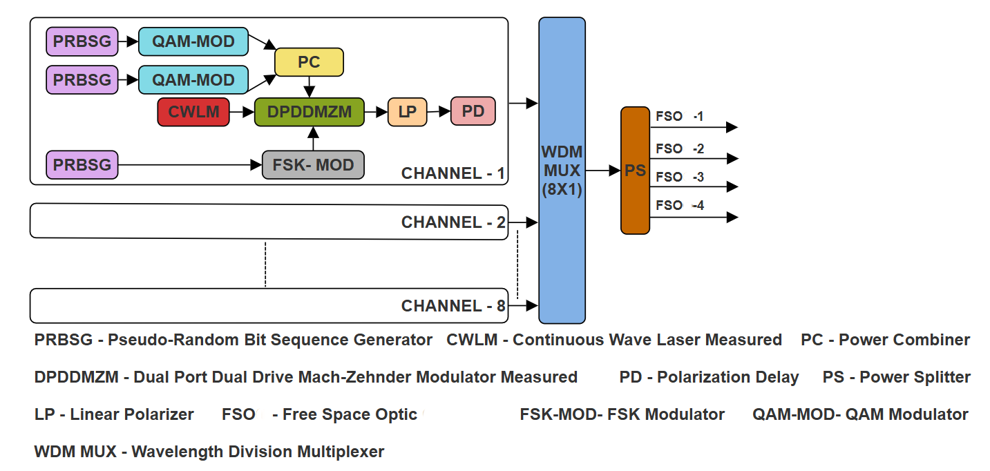
Fig. 1. Transmitter block diagram of a proposed WDM-MIMO-FSO (8 × 4 × 200 Gbps) system.
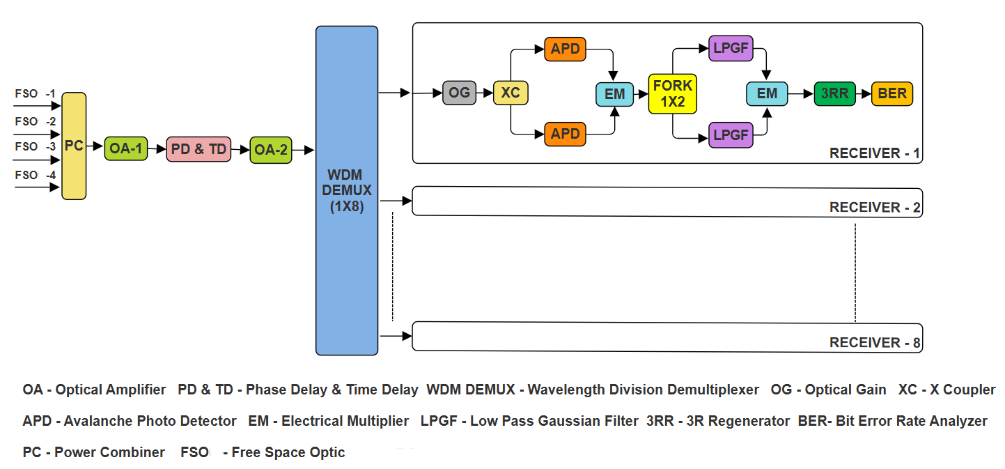
Fig. 2. Receiver block diagram of a proposed WDM-MIMO-FSO (8 × 4 × 200 Gbps) system.
in confirming reliable FSO links by synchronising signals to facilitate in-phase summation and minimise BER under severe weather conditions. The delayed signals are amplified by an optical amplifier, and the eight channels are demultiplexed by a WDM demultiplexer. These signals are fed into the respective receivers. Each receiver has an optical gain component to provide the proper gain to the received signals.
The gained signals are given to the X-coupler. The outputs of the coupler are connected to avalanche photo detectors (APDs) for detection. Detected signals are multiplied by an electrical multiplier and then fed into lowpass Gaussian filters to remove ripples in the received signals. The received electrical signal has amplitude variations that represent the modulated data. Though it is a composite signal, the noise and distortion introduced by the FSO channel still affect the eye opening, Q factor, and SNR. Thus, BER estimation based on the Q factor is performed for the proposed system. The 3RR is used to reamplify, re-shape, and re-time the received information signal. Eye height, BER, and quality factors are investigated using a BER analyser.
2.1. Effect of atmospheric instability in the proposed system
The performance of the FSO channel is degraded by atmospheric instability. The presence of particles in the air is called haze. These particles vary in size and remain in the air for long periods, which affects optical signals [22]. The rain is also an important element to degrade the signal in FSO channel. Multiple refractions and reflections of light occur in raindrops of different sizes [22]. Fog is an important weather element, defined as a cloud of water or smoke particles that affects optical signals and reduces the quality of received signals [23]. With respect to the Kim and Kruse model, the specific attenuation is given in (1) [22, 24]:

where V is the visibility range in km, λ is the wavelength in nm, and q is the size of the distribution of scattering particles in nm [22, 24]. In the Kruse model, the q values are calculated by the (2) [22, 23]:
To calculate the values of q, the Kim model is given in (3) [22, 23]:
The proposed 6.4 Tbps WDM-MIMO-FSO research has been examined under weather conditions, including clear, haze, rain, and fog. The attenuation values considered in the proposed system are listed in Table 1. The link range is also extended to a maximum of 113 km under clear weather and 2.25 km under heavy fog. These scenarios are investigated by employing the QAM-FSK dual-modulation technique in a WDM-MIMO-based FSO system with eight independent channels.
Attenuation values of the proposed system for diverse atmospheric conditions [16, 17, 20, 21].
| Haze | Rain | Fog | |
|---|---|---|---|
| Light | 1.537 dB/km | 6.27 dB/km | 9 dB/km |
| Medium | 4.285 dB/km | 9.64 B/km | 16 dB/km |
| Heavy | 10.115 dB/km | 19.28 dB/km | 22 dB/km |
3. Simulation setup
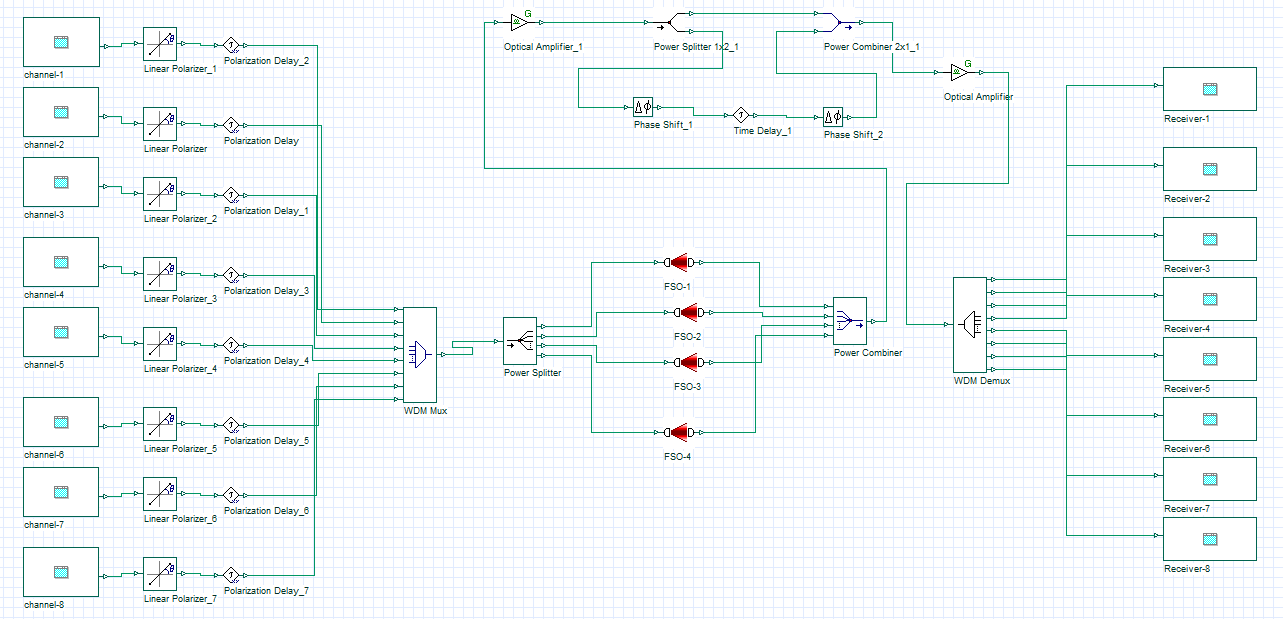
Parameter selection plays an important role in achieving the maximum link range while minimising geometric losses in the FSO system. Table 2 presents the simulation parameters for the proposed work. Figure 3 illustrates the proposed 6.4 Tbps WDM-MIMO-FSO sender and receiver simulation model of the Optisystem
simulator. The system has eight channels with a wavelength of 850 to 864 nm and a 250 Gbps bandwidth. The continuous wave laser power of this system is 10 dBm. The data transmission rate per channel is 200 Gbps and the system net transmission is 6.4 Tbps (8 × 4 × 200 Gbps).
The simulation subsystems of the proposed work are depicted in Fig. 4 and Fig. 5. The QAM-FSK dualmodulation and optical modulation are illustrated in Fig. 4 as a channel subsystem. In the receiver subsystem, Figure 5 shows the receiver setup of each channel.
4. Results and discussion
The achievement of the increased link range, minimised BER, better SNR, and high-transmission rate are the distinct advantages of the proposed 6.4 Tbps WDMMIMO-FSO system in diverse weather conditions such as clear weather (CW), light haze (LH), medium haze (MH), heavy haze (HH), light rain (LR), medium rain (MR), heavy rain (HR), light fog (LF), medium fog (MF), and heavy fog (HF). The following sections discuss the results of the above weather conditions in detail.
Simulation parameter values of the proposed work.
| Parameter | Values |
|---|---|
| Wavelength | 850–864 nm |
| Number of channels | 8 |
| Data transmission rate per channel | 200 Gbps |
| Bandwidth | 250 Gbps |
| Visibility range | 113 km |
| CWLM – power | 10 dBm |
| Transmitting antenna aperture diameter | 50 mm |
| Receiving antenna aperture diameter | 75 mm |
| Beam divergence angle | 0.025 mrad |
| Atmospheric attenuation (clear weather) | 0.14 dB/km |
| PIN photodiode ionization ratio | 0.9 |
| PIN responsivity | 1 A/W |
| Dark current | 10 nA |
| Sequence length | 128 bits |
| Samples per bit | 64 |
| Number of samples | 8192 |
Fig. 3. Transmitter and receiver simulation model of the proposed system.
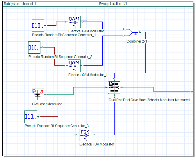
Fig. 4. Channel subsystem.
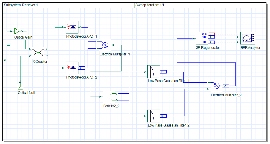
Fig. 5. Receiver subsystem.
4.1. Results under clear weather conditions
In clear weather, 0.14 dB/km is an attenuation value used in the proposed system. Under this condition, the highest link range achieved by this system is 113 km. The link range vs. Q factor values of the system are illustrated graphically in Fig. 6. In this graph, at the 113 km link range, the maximum Q factor value is obtained as 22 for the 856 nm channel, and the minimum Q factor value is obtained as 14 for the 858 nm channel. At the range of 113 km, Figure 7 indicates that the highest SNR of 39 dB is obtained for the 862 nm channel and the lowest SNR of 12 dB is attained for the 858 nm channel.
4.2. Results under haze weather conditions
Under hazy weather, the proposed system attenuations are considered as 1.537 dB/km for light haze, 4.285 dB/km for medium haze, and 10.115 dB/km for heavy haze. In the case of light haze, this system accomplishes up to 19.2 km of the visibility range.
The link range vs. Q factor values of the system for the light haze case are exemplified clearly in Fig. 8, which shows that in the 19.2 km range, the greatest Q factor of 22.97 is attained for the 856 nm channel and the minimum Q factor value of 15 is attained for the 858 nm channel. From the point of SNR concern, the maximum SNR of 42.99 dB is produced by the 862 nm channel and the minimum SNR of 9.8 dB is produced by the 852 nm channel, as illustrated in Fig. 9.
In medium haze, this system covers up to 8.3 km of the visibility range. The link range vs. Q factor values of the system for the medium haze case are shown in Fig. 10. Figure 10 confirms that in the 8.3 km link range, the greatest Q factor of 23.21 is obtained for the 856 nm
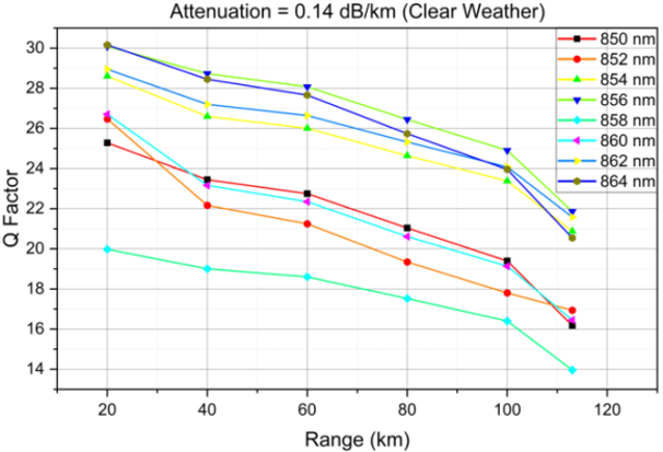
Fig. 6. Link range vs. Q factor (clear weather).
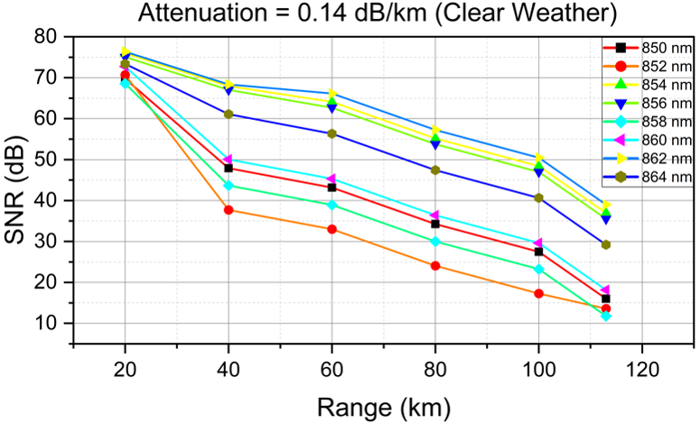
Fig. 7. Link range vs. SNR (clear weather).
channel and the lowest Q factor value of 15 is achieved for the 858 nm channel.
The highest SNR, 43.86 dB, is produced by the 862 nm channel and the minimum SNR, 10.7 dB, is produced by the 852 nm channel, as illustrated in Fig. 11.
In heavy haze, the proposed system reaches up to 4.25 km of the link range. The link range vs. Q factor values of the system for the heavy haze are symbolised in Fig. 12. Figure 12 depicts that, in the 4.25 km range, the greatest Q factor of 19.73 is obtained for the 862 nm channel, and the
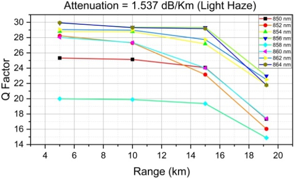
Fig. 8. Link range vs. Q factor (light haze).
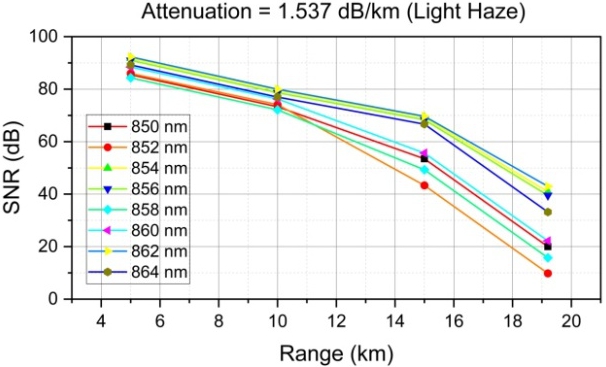
Fig. 9. Link range vs. SNR (light haze).
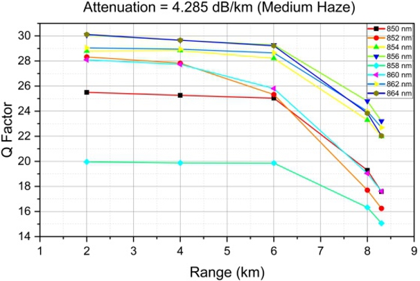
Fig. 10. Link range vs. Q factor (medium haze).
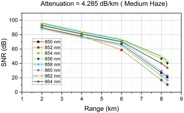
Fig. 11. Link range vs. SNR (medium haze).
lowest Q factor value of 12.14 is attained for the 858 nm channel. In the view of SNR, the maximum SNR of 31.52 dB is produced by the 862 nm channel and the minimum SNR of 4.3 dB is produced by the 858 nm channel, as illustrated in Fig. 13.
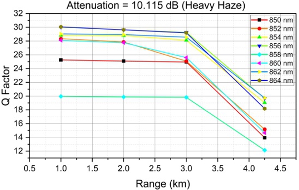
Fig. 12. Link range vs. Q factor (heavy haze).
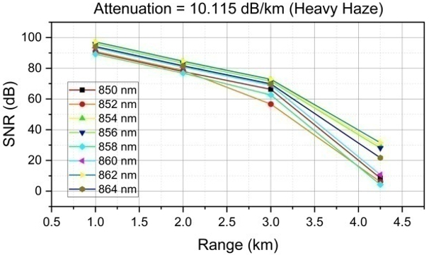
Fig. 13. Link range vs. SNR (heavy haze).
4.3. Results under rain weather conditions
The attenuations are considered for rain atmosphere as 6.27 dB/km for light rain, 9.64 dB/km for medium rain, and 19.28 dB/km for heavy rain. In light rain, the proposed system achieved up to 6.4 km of visibility. The link range vs. Q factor values of the system for light rain is exemplified in Fig. 14. Figure 14 shows that in the 6.4 km range, the greatest Q factor of 20 is achieved for both the 856 and 862 nm channels. The minimum Q factor value of 14.2 is achieved for the 858 nm channel. From the view of SNR, the maximum SNR of 32.7 dB is obtained by the 862 nm channel, and the minimum SNR of 12 dB is obtained by the 860 nm channel, as revealed in Fig. 15. In medium rain, the proposed system carries out up to a 4.6 km range. The link range vs. Q factor values of the system for the medium rain case are indicated in Fig. 16. Figure 16 substantiates that in the 4.6 km range, the high Q factor of 18.12 is achieved for the 860 nm channel and the lowest Q factor value of 14 is acquired for the 858 nm channel. With respect to SNR, the maximum SNR of 25.21 dB is produced by the 860 nm channel and the minimum SNR of 8 dB is produced by the 852 nm channel, as symbolised in Fig. 17.
The proposed system extended its performance to a range of 2.5 km under heavy rain conditions. The link range vs. Q factor values of the system for the heavy rain case is designated in Fig. 18. Figure 18 substantiates that in the 2.5 km visibility range, the elevated Q factor of 18.32 is realised for the 862 nm channel and the least Q factor value of 13.6 is gained for the 858 nm channel. The highest
SNR, 26.1 dB, is produced by the 862 nm channel and the minimum SNR, 9.8 dB, is produced by the 852 nm channel, as represented in Fig. 19.
4.4. Results under fog weather conditions
The proposed system accounts for fog-related signal attenuation with values of 9 dB/km for light fog, 16 dB/km for medium fog, and 22 dB/km for heavy fog. The proposed system reached up to 4.7 km of the visibility range under light fog. The link range vs. Q-factor values of the system for light fog are illustrated in Fig. 20. It shows that the high Q-factor
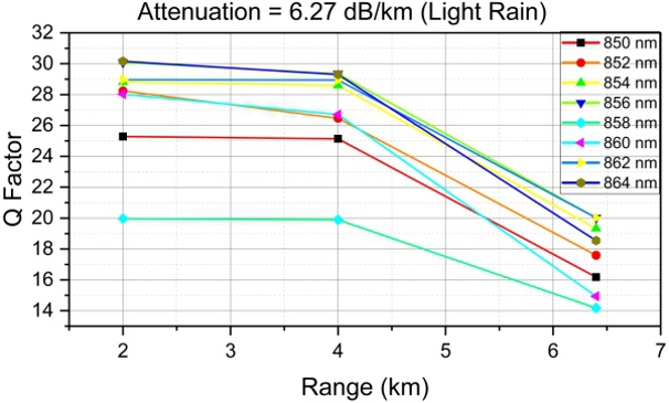
Fig. 14. Link range vs. Q factor (light rain).
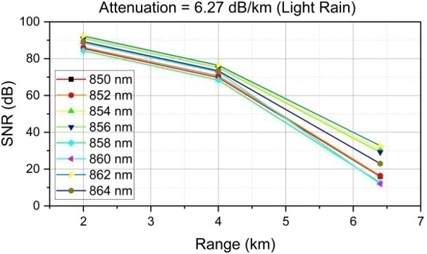
Fig. 15. Link range vs. SNR (light rain).
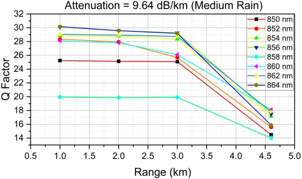
Fig. 16. Link range vs. Q factor (medium rain).
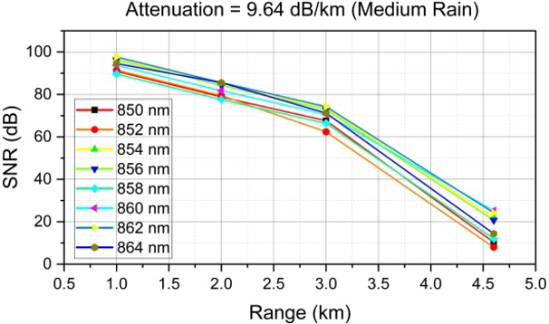
Fig. 17. Link range vs. SNR (medium rain).
value of 20.95 for the 856 nm channel and the low Q-factor value of 15.24 for the 850 nm channel are achieved at a link range of 4.7 km. The greatest SNR, 35.85 dB, is obtained by the 862 nm channel and the minimum SNR, 8.64 dB, is obtained by the 858 nm channel, as shown in Fig. 21.
In medium fog, the proposed system reaches up to 2.9 km of the visibility range. Figure 22 shows the link range vs. Q factor for the system under medium fog conditions and confirms that, within the 2.9 km range, the highest Q factor of 20.51 is achieved for the 856 nm channel, while the lowest Q factor of 14 is obtained for the 858 nm channel. In the view of SNR, the maximum SNR
Fig. 18. Link range vs. Q factor (heavy rain).
of 34.33 dB is produced by the 862 nm channel and the minimum SNR of 11.34 dB is produced by the 850 nm channel, as shown in Fig. 23.
In the case of heavy fog, the proposed system extended its performance up to 2.25 km of the link range. Figure 24 shows the link range vs. Q factor for the system under heavy fog conditions and indicates that, within the 2.25 km range, the highest Q factor of 19.6 is achieved for the 862 nm channel, while the lowest Q factor of 13.2 is obtained for the 858 nm channel. From the view of SNR, the maximum SNR of 31 dB is produced by the 862 nm channel and the minimum SNR of 9 dB is produced by the 858 nm channel, as illustrated in Fig. 25.
Fig. 19. Link range vs. SNR (heavy rain).
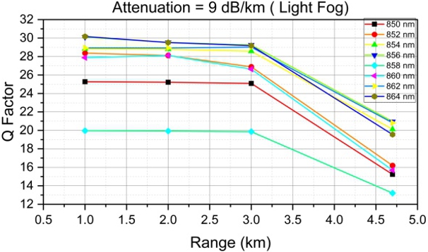
Fig. 20. Link range vs. Q factor (light fog).
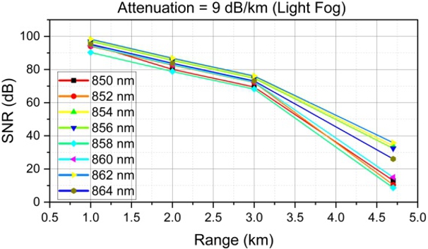
Fig. 21. Link range vs. SNR (light fog).
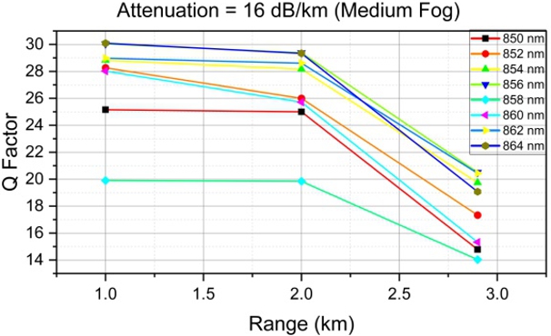
Fig. 22. Link range vs. Q factor (medium fog).
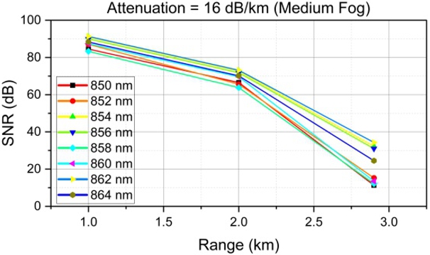
Fig. 23. Link range vs. SNR (medium fog).
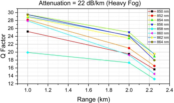
Fig. 24. Link range vs. Q factor (heavy fog).
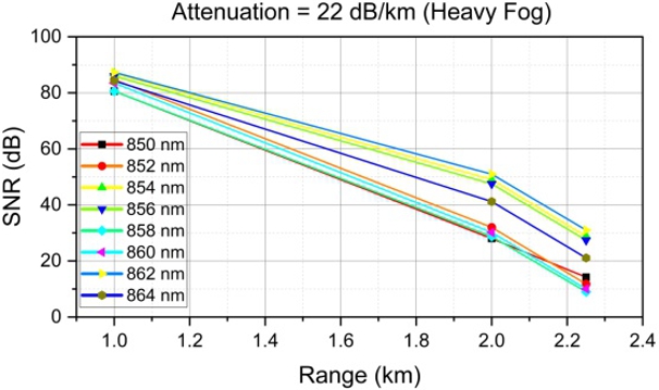
Fig. 25. Link range vs. SNR (heavy fog).
4.5. Results of BER under all atmospheric conditions 5. Conclusions
The proposed dual-modulated, linearly polarised WDMMIMO-based FSO (8 × 4 × 200 Gbps) system under diverse atmospheric conditions achieves minimal BER across all eight channels, as tabulated in Table 3. From Table 3, the prominent minimum BER values attained for all eight channels can be ordered as 856 nm, 862 nm, 854 nm, 864 nm, 852 nm, 850 nm, 860 nm, and 858 nm, respectively. The performance analysis comparison of the proposed work with existing systems is illustrated in Table 4. Table 4 reports that the proposed QAM-FSK dualmodulated, linearly polarised WDM-MIMO-FSO (8 × 4 × 200 Gbps) system achieves performance in allweather environments, extending the visibility range from 2.25 km to 113 km, with the highest Q factors, better SNR, and minimal BER values.
The QAM-FSK dual-modulated, linearly polarised WDMMIMO-FSO system was implemented and simulated under various atmospheric conditions, including clear weather, haze, rain, and fog, achieving a net data transmission rate of 6.4 Tbps across eight independent wavelength channels. Each channel transmitted 200 Gbps of QAM-FSK modulated data through four FSO-MIMO systems. Notably, the system achieved a visibility range of up to 113 km in clear conditions. Under light, medium, and heavy haze, the system maintained link ranges of 19.2 km, 8.3 km, and 4.25 km, respectively. The system achieved link ranges of 6.4 km for light rain, 4.6 km for medium rain, and 2.5 km for heavy rain. For fog, the link ranges were 4.7 km for light fog, 2.9 km for medium fog, and 2.25 km for heavy fog. The results indicate that, across all eight
Channel wise BER values for diverse atmospheric conditions.
|
Weather condition |
Range in km |
Channels / BER | |||||||
|---|---|---|---|---|---|---|---|---|---|
| 850 nm | 852 nm | 854 nm | 856 nm | 858 nm | 860 nm | 862 nm | 864 nm | ||
| CW | 113 | 1.68e-59 | 5.43e-65 | 3.14e-97 | 2.41e-106 | 4.57e-45 | 2.01e-61 | 1.04e-103 | 3.12e-94 |
| LH | 19.2 | 5.52e-68 | 1.28e-58 | 9.19e-106 | 3.64e-117 | 8.40e-51 | 1.97e-68 | 1.53e-112 | 1.51e-105 |
| MH | 8.3 | 7.45e-70 | 4.81e-60 | 1.37e-107 | 1.66e-119 | 4.92e-52 | 5.58e-70 | 2.00e-114 | 4.99e-108 |
| HH | 4.25 | 6.36e-45 | 1.24e-52 | 2.58e-81 | 1.17e-86 | 1.11e-34 | 3.06e-49 | 4.33e-87 | 2.39e-74 |
| LR | 6.4 | 1.56e-59 | 6.84e-70 | 9.11e-84 | 1.19e-89 | 2.38e-46 | 4.74e-51 | 1.15e-89 | 2.55e-77 |
| MR | 4.6 | 3.17e-48 | 1.72e-55 | 1.62e-66 | 6.18e-69 | 2.67e-45 | 5.69e-74 | 1.72e-71 | 2.79e-57 |
| HR | 2.5 | 7.94e-52 | 1.50e-58 | 3.19e-70 | 2.58e-73 | 9.18e-43 | 2.33e-68 | 2.08e-75 | 2.02e-61 |
| LF | 4.7 | 4.08e-53 | 1.23e-59 | 1.75e-90 | 6.29e-98 | 1.35e-40 | 3.99e-56 | 1.09e-96 | 1.25e-85 |
| MF | 2.9 | 3.93e-50 | 7.09e-68 | 3.17e-87 | 6.64e-94 | 1.74e-45 | 1.22e-53 | 2.73e-93 | 1.43e-81 |
| HF | 2.25 | 8.18e-56 | 6.59e-62 | 5.70e-80 | 5.08e-85 | 1.41e-40 | 2.94e-48 | 1.12e-85 | 9.80e-73 |
Performance comparison of the proposed work with the previous works.
| Reference/ Year |
Technique used | Net Data rate (Tbps) |
Weather conditions / Maximum visibility range in km | |||||||||
|---|---|---|---|---|---|---|---|---|---|---|---|---|
| CW | LH | MH | HH | LR | MR | HR | LF | MF | HF | |||
| Ref. [16] / 2020 |
WDM-DP-QPSK modulation |
6.4 | 92 | 17.6 | 7.9 | 3.9 | 5.75 | 4.1 | 2.25 | 4.3 | 2.65 | 2 |
| Ref. [17] / 2021 |
DWDM- MDRZ/DRZ/CSRZ modulation |
1.28 | 8 | 1.4 | 1.4 | 1.2 | 2 | 1.65 | 1 | 0.8 | 0.8 | 0.75 |
| Ref. [18] / 2021 |
OFDM-FSO hybrid W-MDM |
0.08 | 32 | − | − | − | − | − | − | 2.8 | − | 1.75 |
| Ref. [19] / 2022 |
MDM-WDM -DP- QPSK modulation |
1 | 20 | − | − | − | − | − | − | 2 | 1.5 | 1.2 |
| Ref. [20] / 2022 |
Hybrid SAC- OCDMA-PDM- FSO-EDW code |
0.06 | 4 | 2.6 | 1.8 | 1.16 | 1.5 | 1.18 | 0.76 | 1.22 | 0.86 | 0.68 |
| Ref. [21] / 2023 |
4 OAM beams PDM-OQPSK |
0.08 | 6 | − | − | − | 2.1 | 1.65 | 1.05 | 1.7 | 1.2 | 0.95 |
| Proposed work |
QAM-FSK dual- modulated WDM- MIMO-FSO |
6.4 | 113 | 19.2 | 8.3 | 4.25 | 6.4 | 4.6 | 2.5 | 4.7 | 2.9 | 2.25 |
wavelength channels and under various adverse atmospheric conditions, the proposed system demonstrates a superior Q-factor, high SNR, and low BER compared to previous studies. This system can support hightransmission-rate requirements for FSO wireless links. Future research on integrating additional optical multiplexing techniques and alternative modulation schemes in MIMO configurations may further enhance the efficiency of the FSO system.
References
[1] Yarra, N. S. F. M. & Avaninathan, S. R. Spectrum-sliced wavelength division multiplexing based free space optical communication employing differential quadrature phase-shift keying . Preprint v3 (2022). https://doi.org/10.21203/rs.3.rs-2173577/v3
[2] Parkash, S., Banga, A. & Kumar, D. Performance enhancement of DWDM FSO system under diverse weather conditions with optimized modulation format . Int. J. Eng. Appl. Sci. Technol. 7, 147–155 (2022). https://doi.org/10.33564/IJEAST.2023.v07i09.022
[3] Kaur, G. & Malhi, K. S. Performance investigations on spectrum sliced wavelength division multiplexing free space optical communication. J. Emerg. Technol. Innov. Res. 5, 985–992 (2018). https://www.jetir.org/papers/JETIR1808445.pdf
[4] Karpagarajesh, G. et al. Investigation of digital video broadcasting application employing the modulation formats like QAM and PSK using OWC, FSO, and LOS-FSO channels. Alex. Eng. J. 61, 647– 657 (2022). https://doi.org/10.1016/j.aej.2021.06.038
[5] Huang, X. H. et al. WDM free-space optical communication system of high-speed hybrid signals. IEEE Photon. J. 10, 1–7 (2018) https://doi.org/10.1109/JPHOT.2018.2881701
[6] Karpagarajesh, G. & Vijayaraj, M. Blocking probability in alloptical WDM network using IMCA. Circuits Syst. 7, 1068–1077 (2016). https://doi.org/10.4236/cs.2016.76090
[7] Jose, T., Du John, V. & Pandiaraj, S. Performance comparison of WDM MIMO RoFSO links for 5G applications. Trends Sci. 19, 4184–4184 (2022). https://doi.org/10.48048/tis.2022.4184
[8] Karpagarajesh, G., Blessie, A. & Krishnan, S. Performance assessment of dispersion compensation using fiber Bragg grating (FBG) and dispersion compensation fiber (DCF) techniques . Inf. MIDEM 51, 215–223 (2021). https://doi.org/10.33180/InfMIDEM2021.402
[9] Darusalam, U., Raj, A. B., Zulkifli, F. Y., Priambodo, P. S. & Rahardjo, E. T. Performance of free-space optical communication systems using optical amplifiers under amplify-forward and amplify-received configurations. Makara J. Technol. 24, 117–124 (2020). https://doi.org/10.7454/mst.v24i3.3648
[10] Arora, D., Saini, H. S., Bhatia, V. & Kaur, J. Enhanced spectrum slicing: Wavelength division multiplexing approach for mitigating atmospheric attenuation in optical communication Opt. Quantum Electron. 54, 258 (2022). https://doi.org/10.1007/s11082-022-03544-8
[11] Ramya, G., Gopi, N. & Avaninathan, S. R. Spectrum slicing WDM for FSO communication system. Int. J. Emerg. Technol. Innov. Res. 6, 459–465 (2019). https://www.jetir.org/papers/JETIR1905D67.pdf
[12] Khan, M. F. N. et al. FSO communication: Benefits, challenges, and its analysis in DWDM communication system. Sir Syed Univ. Res. J. Eng. Technol. 9, 45–53 (2020). https://doi.org/10.33317/ssurj.181
[13] Saleh, M. A., Abass, A. K. & Ali, M. H. Enhancing performance of WDM-RoFSO communication system utilizing dual channel technique for 5G applications. Opt. Quantum Electron. 54, 497 (2022). https://doi.org/10.1007/s11082-022-03857-8
[14] Sheikh, S., Tripathi, A. & Verma, A. Performance analysis of high speed spectrum sliced FSO system. Int. J. Res. Eng. Sci. Manag. 2, 381–384 (2019). - https://www.ijresm.com/Vol.2_2019/Vol2_Iss4_April19/IJRESM_V2_I4_107.pdf
[15] Jose, T., Du John, V. & Pandiaraj, S. Performance analysis of WDM MIMO RoFSO links for 5G applications. Telkomnika 20, 260–267 (2022). https://doi.org/10.12928/TELKOMNIKA.v20i2.22829
[16] Singh, M., Malhotra, J., Rajan, M. M., Dhasarathan, V. & Aly, M. H. Performance evaluation of 6.4 Tbps dual polarization quadrature phase shift keying Nyquist-WDM superchannel FSO transmission link: Impact of different weather conditions. Alex. Eng. J. 59, 977–986 (2020). https://doi.org/10.1016/j.aej.2020.03.031
[17] Sharma, A. & Kaur, S. Performance analysis of 1280 Gbps DWDM-FSO system employing advanced modulation schemes. Optik 248, 168135 (2021). https://doi.org/10.1016/j.ijleo.2021.168135
[18] Singh, M. et al. Performance evaluation of a 4 × 20-Gbps OFDMbased FSO link incorporating hybrid W-MDM techniques. Front. Phys. 9, 746779 (2021). https://doi.org/10.3389/fphy.2021.746779
[19] Anuranjana, Kaur, S., Goyal, R. & Chaudhary, S. 1000 Gbps MDM-WDM FSO link employing DP-QPSK modulation scheme under the effect of fog. Optik 257, 168809 (2022). https://doi.org/10.1016/j.ijleo.2022.168809
[20] Singh, M., Aly, M. H. & Abd El-Mottaleb, S. A. Performance analysis of 6 × 10 Gbps PDM-SAC-OCDMA-based FSO transmission using EDW codes with SPD detection. Optik 264, 169415 (2022). https://doi.org/10.1016/j.ijleo.2022.169415
[21] Yarra, N. S. V. M., Avaninathan, S. R. & Esakkimuthu, K. 80 Gb/s OAM-PDM-OQPSK FSO system under extensive weather conditions-performance analysis. Optoelectron. Adv. Mat. 17, 446– 460 (2023). https://oam-rc.inoe.ro/articles/80-gbs-oam-pdm-oqpskfso-system-under-extensive-weather-conditions-performanceanalysis/fulltext
[22] Dayal, N., Singh, P. and Kaur, P. Long range cost-effective WDMFSO system using hybrid optical amplifiers. Wirel. Pers. Commun. 97, 6055–6067 (2017). https://doi.org/10.1007/s11277-017-4826-7
[23] Rajput, S. J. & Acharya, Y. B. Performance analysis of 25 Gbps DP-QPSK based Co-OFDM-FSO link incorporating spatial diversity under climate conditions and atmospheric turbulence. Prog. Electromagn. Res. C 133, 151–165 (2023). https://doi.org/10.2528/PIERC23031505
[24] Modalavalasa, S. K., Miglani, R., Chaudhary, S., Tubbal, F. & Raad, R. Developing cost-effective and high-speed 40 Gbps FSO systems incorporating wavelength and spatial diversity techniques. Front. Phys. 9, 744160 (2021). https://doi.org/10.3389/fphy.2021.744160